What Makes a Slotted Waveguide Array Antenna Highly Directional?
A slotted waveguide array antenna achieves exceptional directionality through precise slot positioning that enables constructive interference across its aperture. Unlike conventional antennas, these arrays leverage waveguide propagation combined with strategically machined slots acting as magnetic dipoles. The spacing, orientation, and depth of each slot control amplitude and phase distribution, creating focused electromagnetic beams with minimal sidelobes. This fundamental design principle delivers superior gain and narrow beamwidth, making slotted waveguide arrays indispensable for radar, satellite communication, and defence applications where precision targeting and interference suppression are paramount.
Understanding the Basics of Slotted Waveguide Array Antennas
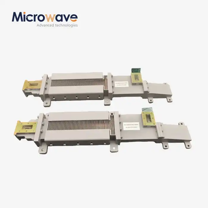
Slotted waveguide array antennas represent a specialised class of directional radiators built around a rectangular metallic waveguide with precisely positioned slots cut into its broad or narrow walls. These slots serve dual purposes: they radiate electromagnetic energy into free space while maintaining the waveguide's structural integrity. The fundamental operational principle relies on electromagnetic wave propagation within the waveguide, where each slot couples energy from the guided mode to create radiating elements distributed along the antenna's length.
When examining the core structure, these antennas differ markedly from patch arrays or horn configurations. The waveguide itself functions simultaneously as both the transmission line and the radiating structure, eliminating the dielectric substrates found in microstrip designs. This integrated approach reduces feed network losses substantially, particularly at frequencies above 12 GHz, where dielectric losses become problematic. We've observed that aluminium or copper alloy construction, often with silver plating, ensures maximum conductivity while maintaining the mechanical robustness necessary for aerospace and maritime environments.
Fundamental Structure and Wave Propagation Mechanics
The rectangular waveguide forms the backbone of these antenna systems, typically supporting the dominant TE10 mode for optimal power transfer. Slots machined into the waveguide walls interrupt surface currents, creating magnetic dipole moments that radiate perpendicular to the slot orientation. The waveguide's internal dimensions determine the cutoff frequency and propagation characteristics, directly influencing operational bandwidth and impedance matching.

Slot Radiation Principles and Phase Control
Each slot functions as a controlled radiator with amplitude and phase determined by its position relative to the standing wave pattern inside the waveguide. Longitudinal slots placed off-centre couple more strongly to the electromagnetic field, while transverse slots require alternating offsets to maintain proper phase relationships. This precise control over individual element excitation enables beamforming capabilities impossible with simpler antenna architectures.
Critical Design Factors Driving Performance
Slot spacing directly affects grating lobe suppression and beamwidth. We typically employ half-wavelength spacing in the guided medium to prevent unwanted radiation lobes. Material selection impacts thermal expansion coefficients, which must remain stable across operating temperature ranges to maintain resonant frequency accuracy. Surface finish quality becomes critical at millimetre-wave frequencies, where skin depth decreases, and resistive losses increase with any surface roughness.
Why Are Slotted Waveguide Array Antennas Highly Directional?
The exceptional directionality of slotted waveguide arrays stems from electromagnetic principles governing phased array behaviour. When multiple radiating elements operate with controlled phase relationships, they produce constructive interference in desired directions while cancelling energy in others. This beamforming capability creates narrow, pencil-like radiation patterns with gains exceeding 30 dBi in properly designed systems. The physical aperture size combined with efficient element distribution determines the achievable beamwidth, with larger apertures yielding tighter beams according to diffraction-limited principles.
Comparing performance metrics against alternative technologies reveals distinct advantages. Patch antenna arrays struggle with feed network losses at X-band and higher frequencies, reducing overall aperture efficiency below 60%. Horn antennas provide excellent performance but require substantial volume, creating aerodynamic penalties for airborne platforms. Parabolic reflectors offer high gain but lack the low-profile advantages critical for flush-mounted installations on aircraft fuselages or ship superstructures.
Constructive Interference and Beamforming Mechanisms
The slotted waveguide array antenna establishes a progressive phase shift between adjacent slots, steering the main beam away from broadside when operating in travelling wave mode. This phase taper, combined with amplitude weighting through slot coupling strength variation, shapes the radiation pattern with precision. Resonant configurations using shorted waveguide terminations create standing wave distributions that maximise efficiency within narrower bandwidths.
Sidelobe Suppression and Gain Optimisation
Achieving sidelobe levels below -30 dB requires sophisticated amplitude tapering, often implementing Taylor or Chebyshev distributions. We manufacture slots with varying dimensions to control individual element excitation, creating the desired aperture illumination. This meticulous control over the electromagnetic field distribution across the antenna aperture minimises unwanted radiation while concentrating energy in the main beam, delivering both high gain and excellent spatial filtering.
Application Advantages in Mission-Critical Systems
These directional characteristics prove invaluable for synthetic aperture radar systems requiring fine azimuth resolution for ground mapping. Satellite communication ground stations benefit from narrow beam widths to maximise signal-to-noise ratios when tracking distant spacecraft. Naval surveillance radars leverage high gain to detect small targets against sea clutter, while the robust all-metal construction withstands harsh maritime environments that would degrade dielectric-based alternatives.
Designing and Optimising Slotted Waveguide Array Antennas for Enhanced Directionality
Optimising these antenna systems demands comprehensive electromagnetic simulation using tools capable of full-wave analysis. We employ computational methods that accurately model slot coupling, mutual interactions, and waveguide discontinuities. These simulations predict radiation patterns, input impedance, and power handling limits before physical prototyping, reducing development cycles and ensuring performance specifications are met.
Material selection directly influences both electrical performance and environmental durability. Aluminium alloys provide excellent strength-to-weight ratios for airborne applications, while copper offers superior conductivity for stationary installations where mass constraints are relaxed. Surface treatments, including silver or gold plating, reduce ohmic losses, which is particularly important at Ka-band and W-band frequencies, where skin depth shrinks to micrometres. Thermal expansion matching between waveguide components and mounting structures prevents mechanical stress that could detune the array during temperature cycling.

Gain Calculations and Pattern Prediction
Accurate gain estimation requires integrating the aperture field distribution and accounting for spillover losses, ohmic dissipation, and impedance mismatch. We calculate directivity from the aperture dimensions and illumination efficiency, then subtract measured losses to predict realised gain. Near-field scanning in our 24-metre anechoic chamber validates these predictions, allowing back-projection algorithms to identify aperture phase errors for iterative design refinement.
Frequency Band Considerations and Material Selection
Operating frequency determines slotted waveguide array waveguide dimensions through cutoff wavelength relationships. X-band systems typically use WR-90 waveguide, while Ku-band applications employ WR-62 or smaller cross-sections. Higher frequencies enable more compact designs but demand tighter machining tolerances—slot length variations exceeding 10 micrometres can shift resonance and disrupt phase progression. Our precision CNC machining capabilities maintain tolerances within 5 micrometres, ensuring performance consistency across production runs.
Customisation for Specialised Requirements
Procurement teams often require tailored solutions addressing unique operational constraints. Customisation options we offer include modified slot patterns for asymmetric beamshaping, enhanced power handling through internal pressurisation, and specialised polarisation configurations using cross-slot or dual-layer architectures. Mechanical interfaces adapt to customer mounting requirements, while environmental sealing meets IP67 standards for external installations. These bespoke modifications ensure integration with existing system architectures while optimising performance for specific mission profiles.
Comparing Slotted Waveguide Array Antennas with Other Solutions in the Market
When evaluating antenna technologies for high-frequency applications, procurement professionals must balance multiple performance parameters against cost and integration complexity. Slotted waveguide arrays occupy a unique position, delivering superior power handling and efficiency compared to printed circuit alternatives while maintaining lower complexity than electronically scanned phased arrays.
Microstrip patch arrays appeal through low manufacturing costs and ease of integration with RF electronics. However, dielectric losses escalate rapidly above 15 GHz, reducing aperture efficiency to 50% or less. The substrate materials also introduce reliability concerns under thermal cycling and high-power operation, with potential delamination or electrical breakdown. We've documented failure modes in patch arrays operating above 100 watts average power, conditions routinely handled by waveguide structures.
Phased array systems provide electronic beam steering without mechanical motion, valuable for rapid target tracking. The trade-off involves substantial complexity through thousands of phase shifters and amplifiers, each introducing insertion loss and requiring dedicated control circuitry. For applications demanding fixed beam directions or accepting mechanical scanning, slotted waveguide arrays achieve comparable directivity at a fraction of the cost and power consumption.
Performance Trade-offs: Fixed Beam vs. Agile Scanning
Applications requiring continuous hemispherical coverage justify the investment in phased arrays, particularly for missile defence and multifunction radars. Maritime navigation and weather surveillance radars achieve adequate coverage through mechanical rotation, making the simplicity and reliability of slotted waveguide arrays more attractive. The absence of active components in waveguide antennas eliminates failure modes associated with semiconductor devices, contributing to mean-time-between-failure figures exceeding 100,000 hours in properly designed systems.
Cost-Effectiveness Analysis for Procurement Decisions
While initial tooling costs for waveguide antenna manufacturing can appear substantial, production economics favour this technology for moderate to large quantities. The robust mechanical structure eliminates concerns about handling damage during installation, reducing field replacement costs. Total cost of ownership calculations must include maintenance requirements, with waveguide antennas typically requiring only periodic visual inspection compared to active array diagnostics and component replacement schedules.

Procurement Guide for Slotted Waveguide Array Antennas
Sourcing these specialised components requires engaging manufacturers with proven expertise in precision machining and electromagnetic design. We recommend evaluating potential suppliers based on their measurement capabilities, particularly access to far-field antenna ranges or near-field scanners that validate performance across the operational frequency band. Manufacturing quality control should include dimensional verification of slot parameters and internal surface finish inspection using borescope techniques.
Lead times vary depending on customisation requirements, with standard X-band and Ku-band slotted waveguide array configurations available within 8-12 weeks, while fully customised designs may require 16-20 weeks for prototype delivery. Our established supply chain relationships ensure consistent availability of high-conductivity aluminium alloys and silver plating services, minimising schedule risks even during periods of material market volatility.
Supply Chain Dynamics and Minimum Order Considerations
Antenna manufacturing economics typically favour minimum order quantities of 10-20 units for custom designs, amortising tooling costs across multiple pieces. We work with procurement teams to structure multi-phase delivery schedules aligning with system integration timelines, maintaining flexibility for design refinements discovered during initial qualification testing. Volume pricing becomes advantageous above 50 units, with potential cost reductions exceeding 30% compared to prototype pricing.
OEM Partnership Opportunities and Customisation Capabilities
Our OEM services extend beyond antenna manufacturing to include integrated feed networks, rotary joints for mechanically scanned systems, and environmental protection radomes. Technical collaboration begins during the concept phase, where our electromagnetic modelling capabilities help optimise antenna specifications within system-level constraints. We provide comprehensive documentation, including measured radiation patterns, mechanical drawings with interface control details, and qualification test reports demonstrating compliance with environmental standards, including MIL-STD-810 for vibration and thermal cycling.
Conclusion
Slotted waveguide array antennas deliver unmatched directionality through fundamental electromagnetic principles governing phased array behaviour. Their all-metal construction provides reliability and power-handling capabilities essential for radar, satellite communication, and defence applications. The combination of high aperture efficiency, excellent sidelobe suppression, and mechanical robustness justifies their selection for mission-critical systems demanding proven performance under extreme environmental conditions. We've outlined key considerations spanning design optimisation, comparative technology assessment, and procurement strategy to support informed decision-making when specifying these sophisticated antenna systems for your next project.
FAQ
1. What factors most significantly influence slotted waveguide antenna directionality?
Aperture size establishes the fundamental diffraction limit, with larger physical dimensions enabling narrower beamwidths. Slot spacing and amplitude distribution control sidelobe levels, while manufacturing precision maintains phase coherence across the array. We've measured beamwidth variations below 0.5 degrees when maintaining slot dimensional tolerances within 5 micrometres.
2. How do these antennas compare to phased arrays for beam steering applications?
Slotted waveguide arrays excel in fixed-beam or mechanically scanned applications, offering superior reliability and lower cost. Phased arrays provide electronic steering speed advantages but require complex feed networks with higher failure rates. The choice depends on scanning speed requirements and budget constraints specific to each application.
3. Can I obtain customised frequency ranges or power ratings?
Absolutely. Our design capabilities span 0.5-110 GHz, with power handling scalable through waveguide size selection and internal pressurisation. Custom projects begin with electromagnetic modelling to validate performance specifications, followed by prototype fabrication and testing in our anechoic chamber. Typical customisation timelines range from 16 to 20 weeks, depending on complexity.
Partner with ADM for High-Performance Slotted Waveguide Array Antenna Solutions
Advanced Microwave Technologies Co., Ltd (ADM) stands ready to support your critical antenna requirements with over 20 years of manufacturing expertise. Our 24-meter anechoic chamber and measurement capabilities up to 110 GHz ensure every Slotted Waveguide Array Antenna meets stringent performance specifications before delivery. We combine ISO 9001:2015 quality management with flexible OEM services, offering customised designs tailored to your exact frequency, power, and mechanical interface requirements. Whether sourcing slotted waveguide array antenna manufacturers for defence radar systems or telecommunications infrastructure, our engineering team collaborates closely with procurement professionals to optimise specifications and delivery schedules. Contact craig@admicrowave.com today to discuss your project parameters and request detailed technical proposals backed by measured performance data.
References
1. Balanis, Constantine A. Antenna Theory: Analysis and Design, Fourth Edition. Wiley, 2016.
2. Elliott, Robert S. Antenna Theory and Design, Revised Edition. IEEE Press, 2003.
3. Mailloux, Robert J. Phased Array Antenna Handbook, Third Edition. Artech House, 2017.
4. Skolnik, Merrill I. Radar Handbook, Third Edition. McGraw-Hill Education, 2008.
5. Pozar, David M. Microwave Engineering, Fourth Edition. Wiley, 2011.
6. Jamnejad, Vahraz and Kim, Yunjin. "Slotted Waveguide Array Antennas for Deep Space Communications." IEEE Antennas and Propagation Magazine, vol. 55, no. 4, 2013.