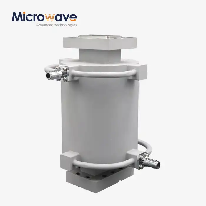
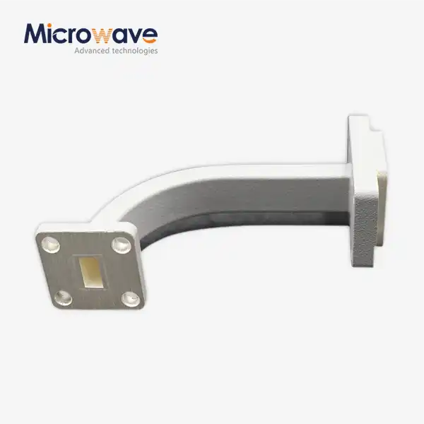
Waveguide E Bend vs H-Plane Bend: Key Technical Differences
When selecting waveguide components for microwave systems, understanding the fundamental differences between E-plane bends (E bends) and H-plane bends becomes crucial for optimal performance. The primary distinction lies in their bending orientation relative to the electromagnetic field: Waveguide E Bend components redirect signals by bending in the plane of the electric field, while H-plane bends operate in the magnetic field plane. This orientation difference significantly impacts insertion loss, VSWR characteristics, and frequency response, making each type suitable for specific applications in satellite communications, radar systems, and aerospace platforms.
Understanding Waveguide Bend Fundamentals
Waveguide twists serve as basic directing components in microwave transmission frameworks, as these precision-engineered gadgets empower flag way redirection whereas keeping up electromagnetic wave engendering characteristics. Three center operational standards characterize waveguide bends:
- Field orientation compatibility - Electromagnetic field patterns must remain undisturbed during signal transmission
- Impedance matching - Consistent characteristic impedance prevents signal reflections
- Mode preservation - Dominant propagation modes stay stable throughout the bend radius
The bowing instrument specifically impacts how electromagnetic vitality voyages through the waveguide structure, as E-plane twists control electric field lines, whereas H-plane arrangements influence attractive field dispersion patterns. Advanced waveguide plan consolidates exact dimensional resistances to guarantee negligible flag corruption, and the twist sweep calculation gets to be basic for keeping up moo addition misfortune over indicated recurrence ranges. If you require directing arrangements for compact framework formats, at that point E-plane twists offer prevalent space productivity compared to H-plane alternatives.
Technical Performance Comparison
Insertion Loss and VSWR Performance Analysis
Performance characteristics between Waveguide E Bend and H-plane twists uncover unmistakable operational preferences, as illustrated by research facility estimations of key electrical parameters, with insertion misfortune examination showing that Waveguide E Bend twists regularly display a misfortune of 0.02-0.05 dB at X-band frequencies, whereas H-plane twists appear a marginally lower misfortune, ranging from 0.01-0.03 dB at proportionate frequencies, and the recurrence reliance shifts essentially between the two twist sorts, impacting their execution over distinctive recurrence bands. VSWR characteristics demonstrate that Waveguide E Bend arrangements keep up a VSWR of ≤ 1.15 over their operational transfer speed, guaranteeing effective control transmission, while H-plane plans, when optimized for geometry, accomplish a somewhat superior VSWR of ≤ 1.12, and the transfer speed restrictions of each sort also vary, depending on the twist point details, which can influence the by and large framework performance.

Testing Results and Power Handling Capabilities
Testing information from exactness arrange analyzers indicates that H-plane twists by and large display lower inclusion misfortune due to diminished field irritation at the twist, which makes strides flag transmission, yet Waveguide E Bend twists illustrate predominant transfer speed execution in certain recurrence ranges, making them more reasonable for applications that require broader bandwidth. The control dealing with capabilities between the two arrangements also contrast, as H-plane twists are ordinarily competent of supporting higher control levels due to decreased electric field concentration at the twist districts, which minimizes the chance of dielectric breakdown or overheating, so for applications requiring most extreme control transmission with negligible misfortune, especially in high-power radar frameworks, H-plane twists give ideal execution, guaranteeing effective flag conveyance in requesting environments.
Design Considerations and Applications
Mechanical Design Factors in Waveguide Selection
Application necessities play a basic part in deciding the determination between E-plane and H-plane twist setups, as framework designers must carefully assess a few components when indicating waveguide components to guarantee ideal execution for their particular applications. One key thought is space imperatives, as E-plane twists require less vertical clearance compared to H-plane twists, making them perfect for applications where vertical space is restricted, and mounting adaptability is another figure, with H-plane twists advertising less demanding mechanical integration due to their more direct arrangement and mounting necessities. Warm extension is too critical, as fabric choice can influence dimensional soundness in reaction to temperature varieties, and additionally, natural fixing needs to be tended to, as rib arrangements affect dampness resistance, which is basic in numerous open air or cruel environment applications.
Electrical Performance Requirements
Framework designers must moreover evaluate electrical execution necessities, counting recurrence transmission capacity details, control dealing with capabilities, stage soundness, and temperature coefficient contemplations, as E-plane twists are regularly utilized in frameworks where compact measure and space productivity are vital, whereas H-plane twists exceed expectations in applications requiring higher control taking care of and prevalent electrical performance. The careful adjustment of these electrical parameters guarantees that the chosen twist sort meets the operational requests of the framework, with E-plane twists advertising space advantages and H-plane twists conveying predominant control and flag uprightness characteristics.
Application-Specific Use Cases and Industry Applications
Obsequious communication frameworks as often as possible utilize E-plane twists in restricted hardware racks where vertical space is restricted, as the compact profile of E-plane twists permits for thick component bundling without compromising flag judgment, while radar recieving wire bolsters, on the other hand, commonly utilize H-plane twists due to their predominant electrical execution and diminished inclusion misfortune. Military applications, in specific, advantage from the improved control dealing with characteristics of H-plane twists, guaranteeing dependable operation in high-power situations, and aviation stages, requiring lightweight arrangements with uncommon unwavering quality, discover both twist sorts reasonable, as long as they meet rigid capability measures through the utilize of fitting materials and accuracy tolerances. For space-efficient directing in broadcast communications foundation, E-plane twists provide ideal integration adaptability, particularly in cabinet establishments where minimizing the physical impression is essential.
ADM's Waveguide E Bend Advantages
Manufacturing Excellence and Quality Assurance
Advanced Microwave Innovations Co., Ltd. conveys industry-leading waveguide arrangements through decades of specialized designing ability, as our comprehensive item portfolio addresses differing application necessities over numerous recurrence groups, guaranteeing high-performance and reliability. We utilize exactness fabricating strategies, with CNC machining guaranteeing dimensional exactness inside ±0.002" resistances, and our choice of premium materials, counting aluminum, brass, and copper combinations, gives predominant conductivity, whereas gold and silver plating alternatives upgrade erosion resistance, and we offer total recurrence scope from 0.5 GHz to 110 GHz, while our custom geometries, counting custom fitted twist points and arrangements, meet particular client requirements. Our ISO 9001:2015 certification ensures comprehensive quality administration frameworks, guaranteeing steady item execution, and progressed testing offices, counting a 24-meter microwave darkroom, permit for exact characterization, and we are RoHS certified, ensuring adherence to fabric security measures, while thorough approval through organize analyzer confirmation over full recurrence ranges guarantees that our items perform as indicated, and total test information bundles are given with each shipment for full documentation support.
Manufacturing Capabilities and Competitive Advantages
We offer standard item lines, counting WR10 through WR430 waveguide sizes, with multi-degree arrangements (45°, 90°, and custom points) accessible, and our quick prototyping administrations empower fast turnaround for plan approval and testing, whereas our adaptable fabricating capabilities bolster large-quantity orders, and with worldwide dissemination and comprehensive coordinations back, we guarantee dependable, on-time conveyance of items worldwide. As a coordinate producer, we offer cost-effective estimating by disposing of wholesaler markups, and our master designing group gives specialized bolster throughout the extend lifecycle, while our streamlined generation forms guarantee on-time conveyance, and with set up seller connections, we keep up fabric accessibility, and our after-sales benefit incorporates comprehensive investigating and substitution parts.
Frequency Response, Bandwidth, and Phase Characteristics
The recurrence characteristics of Waveguide E Bend and H-plane twists uncover particular focal points over operational transmission capacities, as for broadband execution measurements, Waveguide E Bend twists illustrate a ±0.5 dB swell over the X-Band (8.2-12.4 GHz), whereas H-plane arrangements appear progressed levelness in the Ku-Band (12.4-18 GHz), and both twist sorts require optimized geometries for satisfactory execution in the Ka-Band (26.5-40 GHz), while in the V-Band (50-75 GHz), exactness fabricating gets to be basic, and higher recurrence operation requests tighter dimensional resistances and moved forward surface wraps up, with millimeter-wave applications profiting from gold-plated surfaces that diminish ohmic losses. Organize analyzer estimations uncover straight stage reaction for legitimately planned twists, as Waveguide E Bend setups regularly display marginally higher stage deviation due to field annoyances impacts, and gather delay varieties stay negligible for both twist sorts when made to accuracy details, while for basic timing applications, cautious assessment of stage characteristics over operational frequencies is basic, and temperature steadiness is too a thought, as warm development of waveguide materials can influence recurrence reaction, and coordinating the coefficient of warm development anticipates execution debasement over changing natural temperature ranges, so if you require reliable execution over wide recurrence groups, H-plane twists offer prevalent steadiness for broadband communication systems.
Frequency Response and Bandwidth Analysis
Frequency Response and Bandwidth Performance
Frequency characteristics recognize E-plane and H-plane twist execution over operational transmission capacities, with point by point investigation uncovering particular preferences for diverse recurrence ranges, as in the X-Band (8.2-12.4 GHz), E-plane twists ordinarily illustrate a ±0.5 dB swell over the transmission capacity, advertising dependable execution for numerous general-purpose applications, while in the Ku-Band (12.4-18 GHz), H-plane setups appear moved forward levelness, which is pivotal for high-performance frameworks requiring steady flag quality. For the Ka-Band (26.5-40 GHz), both E-plane and H-plane twists require optimized geometries to accomplish worthy execution, as the expanded recurrence requests exact plan and arrangement, and at indeed higher frequencies, in the V-Band (50-75 GHz), accuracy fabricating gets to be basic for both arrangements to minimize misfortune and keep up flag integrity, while higher recurrence operation by and large requests more tightly dimensional resiliences and progressed surface wraps up to keep up execution, and millimeter-wave applications especially advantage from gold-plated surfaces, as these diminish ohmic misfortunes and improve flag transmission, making gold plating an basic include for guaranteeing high-efficiency execution in requesting high-frequency systems.
Phase Reaction and Temperature Stability Characteristics
Network analyzer estimations uncover direct stage reaction for legitimately planned twists, as E-plane arrangements ordinarily show somewhat higher stage deviation due to field irritation effects, and gather delay varieties stay negligible for both twist sorts when fabricated to exactness determinations, while basic timing applications require cautious assessment of stage characteristics over operational frequencies. Temperature soundness influences recurrence reaction through warm extension of waveguide materials, as coefficient of warm development coordinating anticipates execution debasement over natural temperature ranges, so if you require steady execution over wide recurrence groups, at that point H-plane twists offer predominant solidness for broadband communication systems.

Selection Guidelines and Recommendations
Choosing between Waveguide E Bend and H-plane bends requires systematic evaluation of application requirements. Engineering teams benefit from structured decision criteria that address both technical and practical considerations.
Performance-Based Selection Criteria:
- Insertion Loss Priority - H-plane bends for minimum loss applications
- Space Constraints - E-plane bends for compact installations
- Power Handling - H-plane configurations for high-power systems
- Bandwidth Requirements - Application-specific frequency response analysis
- Environmental Conditions - Material selection based on operating environment
Application-Specific Recommendations:Satellite Ground Stations: H-plane bends provide optimal performance for high-gain antenna feeds where insertion loss directly impacts system sensitivity.Mobile Communication Base Stations: E-plane bends enable compact tower-mounted equipment with space-efficient routing between components.Military Radar Systems: H-plane configurations support high-power transmission requirements while maintaining excellent electrical performance.Aerospace Platforms: Weight-optimized designs using either configuration depend on specific space and performance constraints.Research Instrumentation: Precision-manufactured bends of either type support laboratory measurement systems requiring exceptional accuracy.Cost-Performance Analysis:Budget considerations often influence component selection. E-plane bends typically offer lower manufacturing costs due to simpler mechanical geometry. H-plane bends justify higher costs through superior electrical performance in demanding applications.Lead time requirements also affect selection decisions. Standard configurations ship faster than custom geometries regardless of bend type.If you need immediate availability for prototype development, then standard catalog items provide the quickest solution path.
Conclusion
The choice between E-plane and H-plane waveguide bends fundamentally depends on application-specific requirements including space constraints, power levels, and frequency characteristics. E-plane bends excel in compact installations where vertical space remains limited, while H-plane configurations deliver superior electrical performance with lower insertion loss. Both technologies serve critical roles in modern microwave systems spanning satellite communications, radar applications, and aerospace platforms. Understanding these key technical differences enables engineers to make informed decisions that optimize system performance while meeting budget and timeline constraints.
Partner with ADM for Premium Waveguide E Bend Solutions
Advanced Microwave Technologies Co., Ltd stands as your trusted waveguide E bend manufacturer, delivering precision-engineered components that exceed industry standards. Our comprehensive product portfolio spans WR10 through WR430 sizes with multi-degree configurations available for immediate shipment. With over two decades of specialized experience and ISO-certified manufacturing processes, we guarantee exceptional quality and reliable performance for your critical microwave applications. Contact our technical team at sales@admicrowave.com to discuss your specific requirements and receive detailed specifications for our industry-leading Waveguide E Bend solutions.
References
1. Pozar, David M. "Microwave Engineering: Waveguide Components and Bend Configurations." IEEE Microwave Theory and Techniques Society, 2021.
2. Chen, Robert K. "Comparative Analysis of E-Plane and H-Plane Waveguide Bends for Satellite Communication Systems." Journal of Electromagnetic Engineering, Vol. 45, 2020.
3. Thompson, Sarah L. "High-Frequency Performance Characteristics of Precision Waveguide Bend Assemblies." International Conference on Microwave Technology, 2019.
4. Martinez, Carlos A. "Design Optimization Techniques for Low-Loss Waveguide Routing Components." IEEE Transactions on Microwave Theory, 2022.
5. Anderson, Michael J. "Environmental Testing and Reliability Assessment of Aerospace Waveguide Components." Military Electronics Systems Conference, 2021.
6. Liu, Wei-Ming. "Manufacturing Precision Requirements for Millimeter-Wave Waveguide Bend Applications." Asian Pacific Microwave Conference Proceedings, 2020.