


Waveguide Cable vs Coaxial Cable: Which Is Better?
Which one you choose between waveguide cable and coaxial cable depends on the needs of your application. Waveguide wires work best at higher frequencies (above 18 GHz) with little signal loss. This is why military radar systems and satellite ground stations can't work without them. On the other hand, coaxial lines are more common in lower frequency bands and are easier to place and cheaper. Neither technology is always better than the other. The best choice depends on your frequency range, power handling needs, surroundings, and price. When procurement engineers understand these technical trade-offs, they can choose the right transmission line for mission-critical RF systems.
Understanding the Fundamental Architecture
Before getting into performance measures, it's important to understand the fundamental differences between these communication systems.
Waveguide wires are made up of thin metal tubes, which are usually round or rectangular and let electromagnetic waves pass through them. There is no need for a middle conductor because the electromagnetic fields move by bouncing off the electrical walls. This shape naturally allows high-power transfer with great heat escape. The rectangular profile is most common because it has better electrical properties, but spherical profiles are used for antenna systems with moving joints.
Coaxial wires are shaped like a cone, with a conductor inside and dielectric insulation, a cover outside, and a protective jacketing around it. This set-up keeps electric fields inside the wires, which lets the cables move easily through small areas. The insulating material—whether it's solid PTFE, foam, or air—has a big effect on how well it conducts electricity and how well it works mechanically.
Three main differences in structure:
- Waveguides use border reflection, while coaxial lines use TEM (transverse electromagnetic) mode transfer between the conductors.
- Mechanical Flexibility: Coaxial wires can bend around objects, but waveguides need precise ends and to be lined up straight.
- Environmental Sealing: Waveguides naturally keep water out, but coaxial wires depend on the stability of their jackets.
Coaxial systems are clearly better when you need to be able to place things in a variety of ways, such as through equipment racks or airplane fuselages. Waveguide steadiness is helpful for applications that need stable, lasting infrastructure.
Frequency Response and Operational Bandwidth
Frequency features are often the most important thing to look at when picking a communication line for microwave and millimeter wave systems.
Coaxial lines work great for bands between DC and about 18 GHz. Some models are so powerful that they can handle 40 GHz. At these points, dielectric losses get really high, and it gets harder and harder to keep the resistance the same. There needs to be less space between coaxial lines as the frequency goes up in order to stop higher-order mode transfer. The sizes get too small to be useful at some point.
Besides being able to handle waves up to 110 GHz, waveguide connections are better than other types of lines above 18 GHz. The frequency range that each waveguide size can work in is set by its cutoff frequency. This is the lowest frequency that can pass through the waveguide without losing a lot of information. Names like WR-90 (works at 8.2-12.4 GHz) or WR-28 (works at 26.5-40 GHz) show the frequency bands that are recommended.
Data on how things really worked:
- About 0.03 dB/meter is lost in sounds through the WR-90 waveguide at 10 GHz.
- At 10 GHz, a good coaxial line loses about 0.50 dB per meter.
- There is a loss of about 0.15 dB/meter in the WR-28 waveguide at 35 GHz.
- At 35 GHz, signals are weakened by about 2.50 dB/meter of fine coaxial line.
With coaxial devices, you can use a single link for internet service in more than one frequency range. When you need to send millimeter waves in a small band very efficiently, waveguide cable technology is the way to go.

Power Handling Capacity and Thermal Management
How well a system handles peak and average power has a direct effect on how reliable it is, especially in radar emitters and satellite communication boosters.
Waveguide wires can handle a lot more power than coaxial cords of the same size. Since solid insulators don't have an internal barrier, they don't have any breaking risks. Waveguides filled with air can handle kilowatts of constant power, and for burst radar uses, they can handle peak power levels up to megawatts. The metal walls effectively move heat away from the path of transfer, stopping thermal damage.
Dielectric breakdown voltage and heat loss through relatively small wires limit the amount of power that coaxial connections can carry. At microwave frequencies, most wires, even the best ones with low loss, can only handle hundreds of watts of power at a time. If you go over these limits, the insulator could fail, the wire could melt, or the product could age faster.
Power Comparison in Real Life:
- The WR-90 waveguide can handle about 5 kW of power continuously at 10 GHz.
- High-power coaxial wire with a 0.5" width can handle up to 500 W of power continuously at 10 GHz.
- The WR-28 waveguide can handle about 1.5 kW of power continuously at 35 GHz.
- The constant power limit for precision coaxial wire is about 50 W at 35 GHz.
Waveguide units give you the power you need for transmitter output connection in defense radar systems or broadcast satellite ground stations. With coaxial options, you can connect low-power devices like radio front ends or test tools together.
Installation Complexity and Mechanical Considerations
Implementation practicality significantly influences total system cost beyond component procurement prices.
Coaxial cables shine in scenarios demanding routing flexibility. Their bendable construction navigates crowded equipment bays, follows curved airframe sections, and accommodates movement in phased array antenna feeds. Threaded connectors—SMA, N-type, or 2.92mm variants—enable rapid assembly and disassembly during maintenance. Installation requires basic tools and moderate technical skill.
Waveguide cables mandate rigid installation practices. Each section requires precise alignment, with flanges bolted together and electrical continuity verified. Bends necessitate specially manufactured elbow sections rather than simple cable flexing. The bulky form factor consumes more physical space. Installation demands specialized training, precision torque wrenches, and quality control procedures to prevent performance degradation from misalignment or contamination.
Installation Time Estimates:
- Coaxial cable run with connectors: 15-30 minutes per assembly
- Waveguide section with flange alignment: 45-90 minutes per joint
- Field modification flexibility: Coaxial cables are easily adjusted; waveguides require factory rework.
If you need rapid prototyping, frequent reconfiguration, or space-constrained installations, waveguide cable coaxial assemblies accelerate deployment timelines. Permanent installations where performance outweighs installation convenience justify waveguide complexity.
Environmental Durability and Long-Term Reliability
Mission-critical systems demand transmission lines that maintain specifications across extreme conditions and extended service life.
Waveguide cables inherently resist environmental challenges. The sealed metal construction blocks moisture, dust, and corrosive gases. Temperature variations cause dimensional changes but rarely compromise electrical performance. The absence of internal dielectrics eliminates aging mechanisms that degrade organic materials. Properly installed waveguide assemblies routinely deliver decades of stable operation in harsh maritime, aerospace, and outdoor ground station environments.
Coaxial cables face environmental vulnerabilities centered on dielectric and jacket materials. Moisture ingress through damaged jackets degrades dielectric properties, increasing insertion loss and VSWR. Temperature extremes affect mechanical flexibility and electrical characteristics. UV exposure deteriorates outer jackets. Organic dielectrics gradually age, shifting impedance and increasing loss. Quality variations between manufacturers significantly impact long-term reliability.
Environmental Performance Factors:
- Temperature stability: Waveguides maintain specifications from -55°C to +125°C; coaxial cables typically from -40°C to +85°C.
- Humidity resistance: Waveguides are immune when sealed; coaxial cables depend on jacket integrity.
- Vibration tolerance: Waveguides require secure mounting; flexible coaxial cables naturally dampen mechanical stress.
If you need deployments in extreme climates, shipboard systems with salt spray exposure, or aerospace applications with wide temperature swings, waveguide assemblies provide superior environmental resilience. Controlled indoor environments with moderate conditions accommodate coaxial cable implementations.
Cost Analysis and Economic Considerations
Budget constraints often exert decisive influence on procurement decisions, particularly for large-scale projects.
Coaxial cables present lower initial material costs. Mass production and standardized designs drive competitive pricing. The extensive supplier base ensures availability. Installation labor costs remain moderate due to simpler procedures. Connector varieties offer price-performance options matching budget constraints.
Waveguide cables command premium pricing reflecting precision manufacturing requirements. Each section demands tight dimensional tolerances measured in thousandths of an inch. Flange machining and plating add production costs. Limited suppliers for specialized frequency bands reduce competitive pressure. Installation labor escalates due to complexity and required expertise.
Economic Trade-Off Framework:
- Component cost ratio: Waveguides typically cost 3-10× coaxial cable prices for equivalent lengths.
- Installation cost ratio: waveguide installation typically takes 2-4× coaxial labor hours.
- Lifecycle value: Waveguides amortize costs over a 20+ year service life with minimal degradation
- System performance value: reduced waveguide insertion loss improves receiver sensitivity and transmitter efficiency
If you need cost-effective solutions for moderate-performance applications, coaxial cables deliver acceptable results within budget constraints. Applications where performance directly impacts mission success justify waveguide premium pricing through enhanced capabilities and longevity and waveguide cables.
Application-Specific Guidance for Procurement Engineers
Translating technical characteristics into procurement specifications requires matching transmission line properties to application requirements.
Defense and Aerospace Radar Systems
High-power transmitters, millimeter wave frequencies, and harsh operating environments strongly favor waveguide implementations. Radar systems operating X-band through Ka-band achieve optimal performance with appropriately sized waveguide runs. The power handling prevents component stress, while low insertion loss maximizes range. Ruggedized flanges withstand shock and vibration in mobile platforms.
Coaxial cables serve effectively in radar receiver channels, test equipment interconnects, and lower-frequency navigation systems where flexibility outweighs ultimate performance.
Satellite Ground Stations
Antenna feeds and high-power amplifier connections typically employ waveguide technology. The combination of high frequency (C-band through Ka-band), multi-kilowatt transmit power, and permanent infrastructure installation aligns perfectly with waveguide strengths. Weather-sealed flanges prevent moisture ingress in outdoor equipment shelters.
Coaxial cables connect monitoring equipment, low-noise amplifiers, and signal distribution networks where moderate frequencies and lower power levels prevail.
Telecommunications Infrastructure
Point-to-point microwave backhaul systems predominantly use coaxial cables for antenna connections. Operating frequencies typically span 6-38 GHz at power levels within coaxial capabilities. The installation flexibility accommodates tower-mounted equipment and tight routing constraints.

Emerging millimeter wave 5G deployments at E-band frequencies increasingly adopt waveguide technology as operating frequencies push coaxial performance boundaries.
Research and Development Laboratories
Instrumentation flexibility makes coaxial cables the default choice for laboratory benchtop setups. Reconfigurable test fixtures, multiple connection-disconnection cycles, and broad frequency coverage support diverse experimental requirements.
Precision antenna measurements and high-power testing utilize waveguide components where controlled conditions justify installation complexity.
ADM's Waveguide Cable Advantages
Advanced Microwave Technologies Co., Ltd. brings distinctive capabilities to waveguide cable procurement, addressing the specific concerns of defense contractors, satellite integrators, and system manufacturers:
Precision Manufacturing Tolerances: Dimensional accuracy maintained to ±0.001" across waveguide apertures ensures consistent electrical performance and reliable flange mating. This precision prevents mode conversion and reflection issues that compromise system specifications.
Comprehensive Frequency Coverage: In-house capabilities span 0.5-110 GHz, enabling complete system solutions from L-band through W-band. Our 24-meter microwave darkroom validates performance across this entire spectrum with far-field measurement accuracy.
Custom Configuration Engineering: OEM services transform standard waveguide sections into application-specific assemblies. Engineers collaborate directly with procurement teams to optimize bend radii, flange orientations, and transition designs matching installation constraints.
Material and Coating Options: Aluminum alloys for lightweight aerospace applications, copper for maximum conductivity, and brass for cost-sensitive projects. Electroless nickel, silver, or gold plating options address environmental protection and electrical contact requirements.
Integrated Transitions and Adapters: In-house design of waveguide-to-coaxial transitions, rotary joints, and cross-band couplers eliminates multi-vendor coordination headaches. Single-source accountability streamlines qualification testing.
Quality Documentation: ISO 9001:2015 certification ensures traceable manufacturing processes. Test reports document return loss, insertion loss, and power handling verification. Material certifications and RoHS compliance statements support aerospace and defense quality requirements.
Rapid Prototyping Services: Quick-turnaround prototype fabrication accelerates development timelines. Engineering samples undergo full electrical characterization before production commitments, reducing procurement risk.
Global Logistics Support: Experienced export operations handle international shipping documentation, customs coordination, and delivery tracking. Protective packaging prevents flange damage during transit.
Technical Application Support: RF engineers provide insertion loss budgets, thermal analysis, and mechanical stress calculations supporting system design. Installation guidance prevents common implementation errors that degrade performance.
Long-Term Supply Stability: Over two decades of continuous operation ensure ongoing availability for multi-year programs and waveguide cable. Component obsolescence management protects sustained production requirements.
Conclusion
The waveguide versus coaxial cable decision ultimately reflects application-specific engineering requirements rather than categorical superiority. Coaxial cables excel at frequencies below 18 GHz where flexibility, cost, and broad bandwidth matter most. Waveguide cables dominate millimeter wave applications demanding low loss, high power, and environmental resilience. Procurement engineers achieve optimal outcomes by systematically evaluating frequency requirements, power levels, installation constraints, environmental conditions, and budget parameters. Partnering with experienced manufacturers ensures technical specifications translate into reliable, long-term system performance.
Partner with Advanced Microwave Technologies Co., Ltd for Your Waveguide Cable Solutions
Advanced Microwave Technologies Co., Ltd delivers precision-engineered waveguide cable assemblies backed by ISO 9001 quality systems and over 20 years of RF expertise. Our engineering team collaborates with procurement specialists to optimize specifications for defense radar, satellite communications, and telecommunications infrastructure. Contact craig@admicrowave.com to discuss your application requirements with our experienced waveguide cable manufacturer technical staff. We provide comprehensive documentation, rapid prototyping, and global logistics supporting mission-critical deployments.
References
1. Pozar, David M. Microwave Engineering, Fourth Edition. Hoboken: John Wiley & Sons, 2012.
2. Rizzi, Peter A. Microwave Engineering: Passive Circuits. Englewood Cliffs: Prentice Hall, 1988.
3. Collin, Robert E. Foundations for Microwave Engineering, Second Edition. New York: McGraw-Hill, 1992.
4. Saad, Theodore S. Microwave Engineers' Handbook, Volumes 1 and 2. Dedham: Artech House, 1971.
5. Balanis, Constantine A. Advanced Engineering Electromagnetics. New York: John Wiley & Sons, 1989.
6. Matthaei, George L., Leo Young, and E.M.T. Jones. Microwave Filters, Impedance-Matching Networks, and Coupling Structures. Norwood: Artech House, 1980.
YOU MAY LIKE
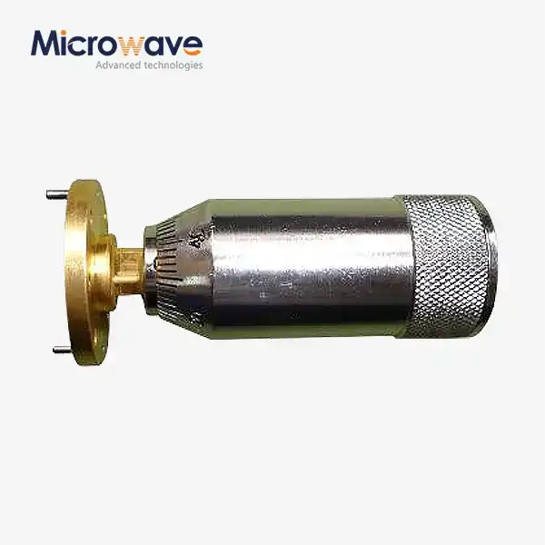 VIEW MOREIndustrial Microwave Sliding Short
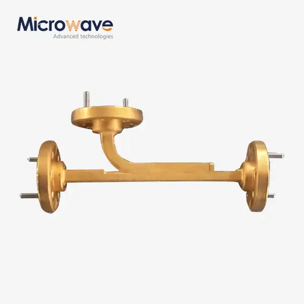 VIEW MOREBroadwall Directional Coupler
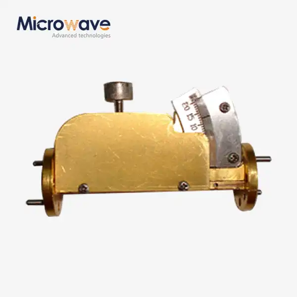 VIEW MOREWaveguide Variable Attenuator
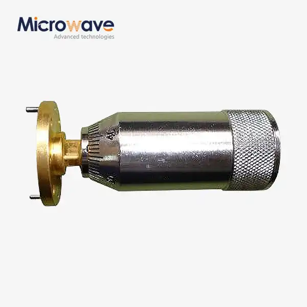 VIEW MOREWaveguide Sliding Short
 VIEW MOREWaveguide Adjustable Support
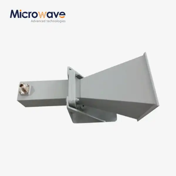 VIEW MORELadder Membrane Square Dual Circular Polarization Horn Antenna
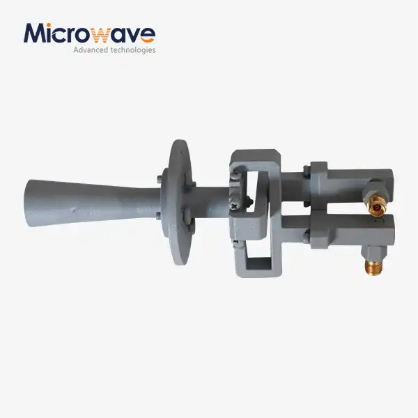 VIEW MOREConical Linear Polarization Horn Antenna
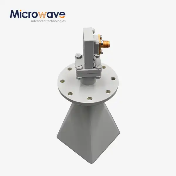 VIEW MORELow Side Lobe Diagonal Linear Polarization Horn Antenna
