





BLOG

Waveguide Harmonic Filter Design for Automotive Workshop
May 7, 2026
Modern automotive systems increasingly demand precise RF signal management as vehicles transition into mobile communication hubs. A waveguide harmonic filter serves as a specialized passive component that suppresses unwanted harmonic frequencies while allowing fundamental signals to pass cleanly—critical for maintaining signal integrity in emerging automotive applications like vehicle-to-everything (V2X) communication, advanced driver-assistance systems (ADAS), and satellite-based connectivity. These filters leverage the unique cutoff properties of waveguide structures to achieve superior harmonic rejection compared to traditional coaxial designs, making them indispensable for automotive workshops integrating next-generation RF systems.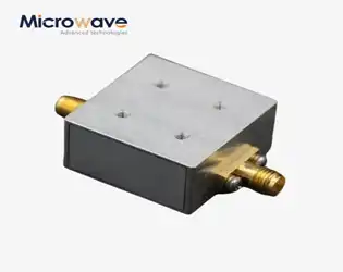
What are the advantages of a coplanar waveguide?
May 6, 2026
Coplanar waveguide technology is very good at improving performance for high-frequency uses, especially in microwave and millimeter-wave circuit designs. This planar transmission line structure has a center wire and two ground planes on the same substrate surface. Compared to traditional microstrip designs, this one allows for better impedance control, less radiation loss, and better signal integrity. The coplanar waveguide design makes production easier and provides excellent electromagnetic field confinement. This makes it the best choice for precision RF measurement applications, aerospace radar systems, and satellite communication equipment. Because it works with surface-mount parts and is easy to fit into small PCB plans, defense, telecommunications, and research institutions can't do without it when they buy things from other businesses today.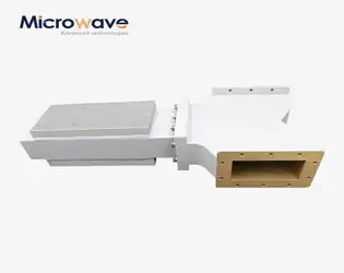
How Waveguide Isolator Improves System Stability in Workshop
May 6, 2026
Waveguide Isolators are very important safety parts in RF and microwave workshops because they allow signals to go only one way while collecting reflected energy that would otherwise make source equipment unstable. These non-reciprocal devices greatly lower frequency drift, keep signal distortion to a minimum, and extend the useful life of expensive test equipment by stopping harmful back-reflections from reaching sensitive amplifiers and oscillators. When Waveguide Isolators are built into calibration stations, antenna measurement systems, and prototype assembly lines, they create stable electromagnetic conditions that make measurements more accurate and cut down on expensive equipment failures.
Waveguide Band Stop Filter Performance Optimization
May 6, 2026
Improving the performance of Waveguide Band Stop Filters is a smart way to make sure that signals in important RF and microwave systems stay intact. The Waveguide Band Stop Filter is a passive part that uses resonant cavity technology to specifically cut down on unwanted frequency bands while keeping the passband sounds very good. This process of optimization includes choosing the right materials, making sure the shapes are correct, managing heat stability, and modeling electromagnetic fields to get rid of sources of interference that slow down the system. Optimized band stop filters provide rejection depths of more than 60 dB with an insertion loss of less than 0.2 dB. This directly leads to better receiver sensitivity and transmitter efficiency in defense radar systems, satellite ground stations, and aerospace communication networks.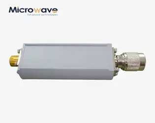
Coaxial Detector for Nuclear Power Plants: Key Features and Selection Tips
April 30, 2026
When nuclear power plants need to watch signals and find radiation with pinpoint accuracy, choosing the right RF detector technology is a mission-critical choice. A Coaxial Detector is a special kind of RF sensor that reliably turns high-frequency microwave signals into DC or low-frequency outputs that can be measured. Compared to optical or basic diode detectors, these ones have better frequency response, better noise insulation, and the durability needed for nuclear settings where safety is very important. Advanced Microwave Technologies Co., Ltd. has designed Coaxial Detectors for these tough uses, mixing point contact diode technology with precisely matched microwave circuits to make sure signal integrity in situations where failure is not a choice.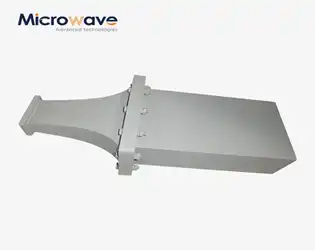
Double Ridge Waveguide Versus Typical Waveguide
April 30, 2026
When choosing microwave transmission parts for wideband systems, the difference between normal rectangular waveguides and double ridge waveguide designs \ determines the structure of the system, double ridge waveguide, and the limits of its performance. The double ridge waveguide has metallic ridges that stick out from the wide walls. This creates a capacitive loading effect that lowers the dominant mode's cutoff frequency while keeping the waveguide's small size. This shape allows multi-octave bandwidth ratios to reach 2.4:1 to 3.6:1, which is higher than the 1.5:1 limit of regular rectangle guides. For procurement teams looking for parts for electronic warfare pods, wideband radar feeds, or RF test systems that need to cover all frequencies without mechanical switching, this structural difference directly means less system complexity, lower integration costs, and more operational flexibility from the C-band to the Ka-band.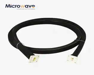
High Power Waveguide Assembly for Satellite and Radar Systems: Complete Guide
April 30, 2026
Modern satellite communication and radar systems are built around high-power waveguide assembly systems, which send electromagnetic data very efficiently at microwave and millimeter-wave frequencies. These special transmission lines are made up of thin metal tubes that are usually copper, aluminum, or brass. They let electromagnetic waves pass through them with little loss through internal reflection. Engineers and procurement teams depend on these units to handle kilowatts of RF power while keeping the purity of the signal in defense, aerospace, and telecommunications applications that need to be reliable and cannot be compromised.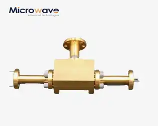
How to Test and Maintain Waveguide Power Dividers for Optimal Performance
April 29, 2026
Testing and maintaining waveguide power dividers requires systematic protocols combining precision measurement equipment with scheduled preventive care. These passive RF components split electromagnetic signals across multiple output paths while preserving signal integrity through controlled insertion loss and isolation. Proper testing involves vector network analysis to measure return loss, insertion loss, isolation, and phase balance against manufacturer specifications, while maintenance encompasses routine inspections, environmental monitoring, and timely cleaning to prevent contamination-induced degradation. Implementing structured testing procedures alongside proactive maintenance schedules ensures mission-critical systems in satellite communications, radar applications, and telecommunications infrastructure maintain peak performance throughout their operational lifecycle.