


BLOG
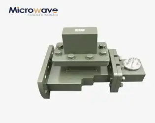
What Makes the Best E-Plane Tee for Waveguide Systems?
January 29, 2026
When waveguide systems fail to deliver consistent signal quality across complex microwave networks, engineers face cascading performance issues that compromise entire communication infrastructures. The best e-plane tee for waveguide systems combines precision junction design, superior impedance matching, and robust power handling capabilities to ensure minimal insertion loss while maintaining signal integrity across frequencies up to 110 GHz. This critical component determines whether your radar system can accurately detect targets, whether your satellite ground station maintains reliable connectivity, or whether your telecommunications network delivers consistent performance under demanding operational conditions.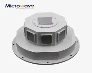
What Applications Use Slotted Waveguide Array Antenna Today?
January 29, 2026
When radar systems fail to detect critical targets in harsh weather, when satellite communication signals degrade over vast distances, or when marine navigation equipment struggles with precise positioning, the root cause often traces back to inadequate antenna technology. Modern microwave systems demand antennas capable of delivering exceptional directivity, minimal signal loss, and reliable performance across extreme operating conditions. Today's Slotted Waveguide Array Antenna technology addresses these critical challenges by providing high-gain, low-loss solutions specifically engineered for the most demanding applications in radar, satellite communications, aerospace, defense, and telecommunications industries.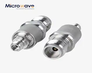
Coaxial Cable Adapter vs Waveguide Adapter: When to Use Which
January 29, 2026
Engineers and system designers frequently encounter a critical dilemma in RF and microwave systems when signal loss reaches unacceptable levels or system integration becomes problematic. The question of selecting between a Coaxial Cable Adapter and waveguide adapter can determine whether your satellite communication link maintains signal integrity or whether your radar system achieves the required detection range. This comprehensive guide addresses the fundamental differences, practical applications, and decision-making criteria that will help you choose the optimal adapter solution for frequencies ranging from DC to 110 GHz, ensuring your system operates at peak performance while avoiding costly mistakes in signal transmission and system compatibility.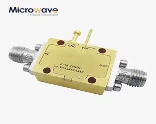
Voltage Controlled Phase Shifter Applications in Phased Arrays
January 28, 2026
When radar systems fail to detect critical targets or satellite ground stations lose signal lock during peak transmission hours, the underlying problem often traces back to inadequate phase control in antenna arrays. The Voltage Controlled Phase Shifter emerges as the essential solution for precise beam steering and signal management across phased array systems. This comprehensive guide explores how voltage controlled phase shifter technology revolutionizes applications in defense, aerospace, telecommunications, and satellite communications, delivering the phase precision that modern systems demand for optimal performance and reliability.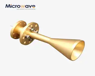
Conical Circular Polarization Horn Antenna Applications Guide
January 28, 2026
When satellite communication networks experience signal degradation during critical operations, or when defense systems struggle with polarization mismatch in adverse atmospheric conditions, the root cause often traces back to inadequate antenna technology. The Conical Circular Polarization Horn Antenna emerges as the definitive solution for professionals facing these challenges, delivering exceptional performance across diverse microwave applications where signal integrity cannot be compromised under any circumstances.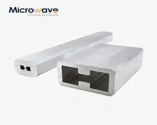
Can a Double Ridge Waveguide Tube Improve Signal Integrity?
January 28, 2026
In high-frequency communication systems, engineers constantly battle signal degradation, reflection losses, and bandwidth limitations that compromise system performance and increase operational costs. When your radar system fails to detect critical targets, when your satellite ground station experiences data corruption, or when your 5G infrastructure suffers from inconsistent coverage, the root cause often traces back to inadequate signal transmission components. The Double Ridge Waveguide Tube emerges as the definitive solution to these persistent challenges, delivering exceptional signal integrity through its innovative dual-ridge architecture that minimizes distortion, reduces reflection losses, and maintains consistent performance across ultra-wide frequency ranges from 1 GHz to 110 GHz.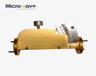
How Does a Waveguide Variable Attenuator Affect VSWR and Loss?
January 26, 2026
Picture this scenario: Your satellite ground station suddenly experiences signal reflections that cause a 2.7 dB drop in transmitted power, or your radar system's receiver protection gets triggered by unexpected signal surges. These real-world disasters stem from poor VSWR management and excessive insertion loss—problems that precision Waveguide Variable Attenuators are specifically engineered to prevent. Understanding how these critical components affect VSWR and insertion loss isn't just academic knowledge; it's the difference between system reliability and catastrophic failure in high-frequency applications ranging from satellite communications to aerospace defense systems.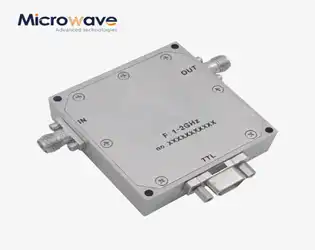
Digitally Controlled Phase Shifter Performance vs Cost Analysis
January 26, 2026
In today's demanding microwave and RF landscape, system designers face a critical challenge when selecting components for radar systems, satellite communications, and phased array antennas. The wrong choice of a Digitally Controlled Phase Shifter can result in signal degradation, increased power consumption, and budget overruns that threaten project viability. This comprehensive analysis examines how to balance performance specifications against cost constraints, helping you make informed decisions that optimize both technical excellence and financial efficiency.
