




Matching Low Phase Noise Amps to Oscillator Requirements
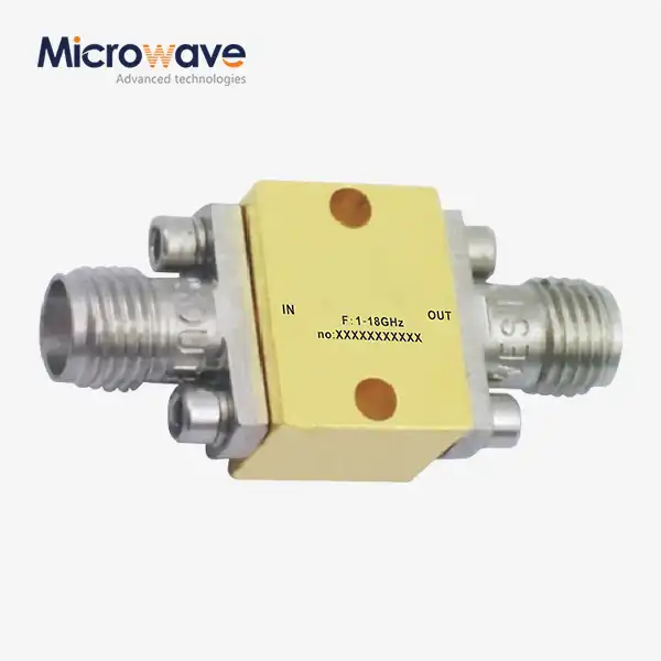
When matching low phase noise amps to oscillator requirements, the amplifier must not introduce noise that the oscillator did not have. First, record the frequency, output power, and phase noise profile of the oscillator. Then choose an amplifier with substantially lower additive phase noise than the oscillator at the offsets your system will require. Then test the gain range, compression margin, and impedance matching. Finally, measure the remaining phase noise to make sure you selected the appropriate option. This document is created for RF engineers, buying managers, and OEM teams comparing specifications, vendors, and evaluation units. This will enable you to shortlist some possibilities before you ask for a price. This option can't be made by gain alone. AM-to-PM conversion, where amplitude variations are converted into phase variations, means that an amplifier contributes its own phase noise and may distort a signal near compression. Noise figure and phase noise are not the same thing either. These are of interest for radar, satellite communications, GPS, frequency synthesizers, PLLs, wireless equipment, electronic warfare, radio astronomy, and test devices.
Step 1: Define the Oscillator and Signal-Chain Requirements
Matching well starts on paper, a long time before any parts are put together on the bench.
Document the Oscillator First
Begin with where the knowledge originated from. Record the output power, phase noise profile, signal type, harmonic content, output impedance, and connection type of the oscillator’s output. The demands of an amplifier are substantially different for a 10 MHz crystal reference and a 10 GHz dielectric resonator oscillator; therefore, the phase noise plot is more relevant than the main frequency. Write down the offsets that matter to your system, e.g., 100 Hz for close-in performance or 100 kHz for the far-out floor. Also check the harmonics. Even if the primary power is seemingly safe, a powerful 2nd harmonic may force an amplifier into compression. -- Make sure all of these numbers are on one page so the engineers and purchasers can both read them.
Place the Amplifier in the Signal Chain
Next, you have to select what the amp is for. This reduces frequency pulling, which is the change in frequency as a consequence of changes in the load. A buffer in an oscillator isolates the source from changes in the load. In a synthesizer, a gain stage is used to elevate an output from a low level to the level required by the following block. A mixer driver is the power that the mixer requires to perform properly. A distribution amplifier feeds more than one branch at a time. Sometimes a preamplifier is needed at the input of the test equipment. Output power, gain, and reverse isolation for each job are weighted differently. A mixer driver requires some room and a buffer must be adequately separated. You’ll define the job up front, and you won’t be shelling out money for features your design will never utilize.
Build a Requirements Matrix
Now, make a list of criteria from those notes. What are the system’s objectives? Noise figure, linearity, output power, return loss, operating temperature, power consumption, packaging, and estimated product volume should all be included. Mark the needed items as required or not required. When a request comes in with this matrix attached, the technical team can rapidly compare it to the solutions that are available rather than sending many emails to fill in the spaces. The matrix removes quotations that are not suitable for the design for consumers throughout the globe. The next block is crucial to include, such as a mixer or filter, since the input level and impedance dictate where low phase noise amps should be working.
Step 2: Understand Low Phase Noise Amplifier Specifications
Many numbers are on a datasheet, but only a few of them give you the answer.
Additive Phase Noise at the Right Offsets
The amount of noise that an amplifier adds to a clean carrier is shown by additive phase noise, also called residual phase noise. Most vendors give it in dBc/Hz at certain offsets, so be careful as you read the table. Before you test, make sure you check the carrier frequency, input power, and test conditions. At different drive levels, the same part may show different numbers. As power is added by noise sources that are not connected to each other, the noise level goes up by 3 dB when an amplifier has the same noise level as the oscillator. In order to avoid this, a lot of designers want the amplifier to make a much smaller contribution than the oscillator at all important offsets. Near the carrier, flicker (1/f) noise is common, and Walls and his colleagues looked into where it comes from in bipolar transistor amplifiers.
Gain Stability, Flatness, and Supply Sensitivity
Gain isn't a set number. It changes with frequency, temperature, and supply voltage. These changes are more important than many datasheets make it seem. Changes in gain can change how a PLL loop works. Before putting the mix together, they change the drive level and the outcome of the conversion. They mess up the calibration of a system that was set up correctly. The process of turning changes in amplitude into changes in phase is linked to changes in gain as well. The AM-to-PM coefficient of a device that is driven close to compression is usually higher and is usually given in degrees per dB. Find out the gain over the whole temperature range and supply tolerance, and make sure the curve is flat over the full frequency range you want to use.
Noise Figure, Linearity, and Interfaces
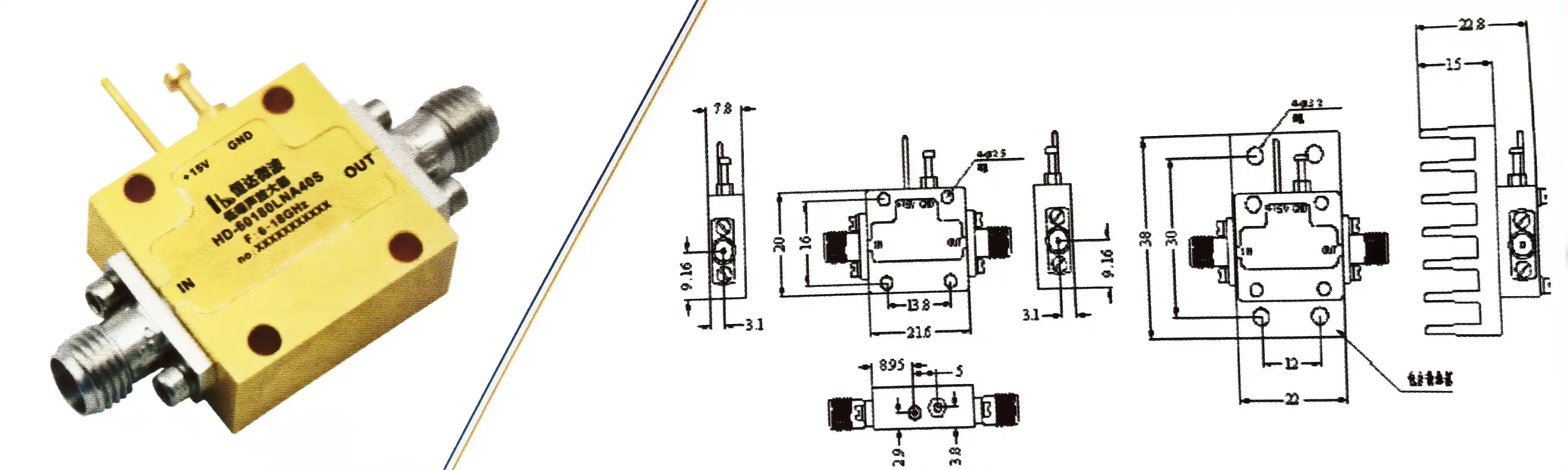
Phase noise and noise figure are two different ways to measure noise. Noise figure shows extra thermal noise that lowers the receiver's sensitivity. Phase noise is the name for noise that is close to a carrier and lowers the purity of the spectrum. Even if an amplifier has a low noise figure and a fine noise figure, it may still add more flicker noise than a part made for signal growth chains. Look over the 1 dB compression point, the third-order intercept (IP3), the harmonic levels, and the spurious signals. Then, check the VSWR at both the input and output. If they are not properly matched, reflections can happen that mess up the oscillator and change the phase. Lastly, make sure you know the type of connector and how it fits mechanically. A coaxial assembly with a loose connector can ruin the choice of an amplifier that was made with care.
Step 3: Match Amplifier Performance to Oscillator Type and Application
A different part of the specification sheet is stressed for each use.
Low Phase Noise Amplifier for Frequency Synthesizers
It is important that a frequency synthesizer's low phase noise amplifier doesn't make the PLL noise floor higher. Outside of the loop, the VCO sets the level, while inside it, reference and detector noise do. Put an amplifier after the VCO or reference. It will add noise at every offset, so pick one whose noise stays below the synthesizer's output noise at the offsets that matter. A stable gain is also important. If the temperature of the gain stage changes, it can turn the drive level into a phase detector or mixer. When checking wideband synthesizers, make sure the gain is flat across the whole tuning range, not just at the center frequency. Also, make sure that the output power stops being back-off from compression at the highest drive point.
Radar, Electronic Warfare, and Satellite Links
With radar, there are new needs for low phase noise amps. Phase noise in the local oscillator chain raises the noise floor near the carrier in Doppler radar. This can hide targets that are moving slowly, so close-in additive noise is important. When the amplifier is turned on and gets warm during pulsed operation, the phase must stay stable. Linearity and output margin are also important in electronic warfare, where more than one signal may be sent along the same chain. If you want to up-convert or down-convert, satellite ground stations and GPS receivers need clean local oscillator signals. Long programs need parts that can be tracked, parts that are safe for the environment, and a steady supply chain. Documents are often asked for early by people who buy defense or satellites, so be ready for that.
Decision Matrix by Oscillator Requirement
For everyday cases, this is the screening matrix I use:
- Stable 10 MHz reference: Close-in phase noise and gain drift lead the list. Flicker noise dominates at low offsets, and small gain shifts with temperature can disturb timing stability. Check supply noise sensitivity, and ask for data measured at offsets below 1 kHz. Buffer isolation also protects the crystal from load changes.
- 1 GHz synthesizer: Residual phase noise and linearity matter most. The amplifier should not lift the PLL output noise, and it should run with output back-off so harmonics and AM-to-PM conversion stay low. Confirm return loss at the load, because reflections can pull the source. Test it at your real drive level.
- Wideband test platform or radar chain: Test platforms need flat gain and consistent spurious levels across the whole span. Radar chains need stable phase, enough output power, and a clear compression margin during pulsed operation. Verify each item at your actual duty cycle and temperature. Lab data should match field conditions closely.
Take this matrix as a first cut, and then let measurements confirm your choice.
Step 4: Use a Practical Selection and Measurement Process
A short, organized process takes a long list of suppliers and turns it into a tried-and-true choice.
Build a Shortlist from Non-Negotiable Requirements
First, look at the things that can't be altered. Frequency range, gain, maximum additive phase noise, output power, return loss, supply circumstances, temperature range, packaging, and availability. Remove any part that does not belong to one of them. Then sort the remainder of the needs by usage. Additive noise could be most significant to a buyer of a synthesizer, whereas phase stability and compression margin might be most relevant to a buyer of a radar. This is how low phase noise amps vary from normal low noise amplifiers or gain blocks. A low noise figure does not necessarily imply that there is low residual phase noise. Look at the measurement plots, the test circumstances mentioned, the guaranteed limits, the manufacturing data, and the quality paperwork to check the claims on the datasheet.
Measure Residual Phase Noise in a Controlled Setup
Phase noise is a function of carrier frequency, drive level, offset, supply quality, and temperature. The only sure method to confirm is in the lab. Configure the test equipment: a phase noise analyzer or cross-correlation system, a clean power supply, attenuators, filters, and shielded connections. Then ensure the power supply is clean. A few of the devices that can measure phase noise include the Keysight E5052B and the Rohde & Schwarz FSWP. Cross-correlation approaches reduce the instrument's own contribution, Rubiola argues. Let's look at the oscillator alone. Compare the oscillator to the amplifier and get the additive element of the amplifier. If you divide the source and compare two routes in quadrature, you eliminate the noise from the source and just have the noise added by the device.
Avoid Common Measurement Errors
A few missteps may deceive a hardworking crew. To ensure that the analyzer is below the predicted result, since an amplifier that is extremely quiet might be masked by the instrument noise floor. Ground loops create hum and spurs, and a moving wire might phase shift during a sweep. Also check the repeatability of the connection by reconnecting the same joint many times and comparing the traces. At low offsets, vibrations from fans or benches are evident, and temperature changes are gradual. Finally, ensure you are comparing apples to apples with the same carrier, input power, supply, and offsets for all parts. If two vendors made plots at different drive levels, you can't compare the figures directly.
Step 5: Protect Phase Noise in the Design and Choose the Right Supplier
If the design or the supplier isn't good, even a strong part can let you down.
Keep the Surrounding RF Design Clean
But even if you choose the correct low phase noise amps, they could not operate properly in a noisy design. Use a low-noise regulator and filtered bias lines. Supply ripple may modify the bias and create spurs. Keep RF lines short, control their impedance, and ensure they are firmly grounded. Also keep the digital and analog circuitry separate. Allow output back-off (often a few dB below compression) to minimize the AM-to-PM shift. Then look at the blocks that follow next. A multiplier adds 20 log N to phase noise. So a times-ten multiplier adds 20 dB. Mixers and filters and distribution networks create noise, vary the levels, etc. Prepare for heat, vibration, enclosure design, and connection integrity. Also, don't simply rate specific pieces of the oscillator, amplifier, and filter chain; look at the whole thing.
Choose Between Standard and Custom Options
There are standard parts that work for your project if the frequency, gain, package, interfaces, and performance are already right. Custom development is useful for frequency ranges that aren't common, very low additive phase noise, small packaging, built-in filtering, special connectors, extended temperature operation, or OEM volumes. You can test a design on a prototype before it goes into full production. ADM offers OEM services with quick prototype turnaround and engineering support. When you send a request for a quote, be sure to include the documentation, delivery, test, and electrical, mechanical, and environmental needs. If you give a supplier a full request, they can answer with a real offer instead of a list of questions.
Evaluate Supplier Capability and Procurement Risk
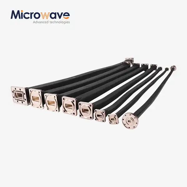
Some of what you buy is technical data. Look at the supplier's knowledge of radio frequency (RF), their ability to measure, their production consistency, their calibration procedures, the availability of evaluation boards, their lead times, their minimum order quantities, and their quality systems. Find out about tracking, export rules, and long-term supply. ADM has been making microwave products for more than 20 years and has labs with measuring tools up to 110 GHz, ISO 9001 certification, RoHS compliance, and a 24m microwave darkroom for testing antennas. These facilities mostly help us with our antenna and waveguide work, but they also show how we measure and keep records. The cables, coaxial assemblies, and waveguide parts that surround an amplifier can also change the phase stability, so having just one supplier for these interfaces can make approvals easier.
Conclusion
When matching low phase noise amps to an oscillator, it's important to keep the source's purity while giving the system the gain, buffering, and drive it needs. From the guide, you should first write down the role of the oscillator and the amplifier. Then, you should read the additive phase noise at the right offsets, along with gain stability, compression, linearity, and VSWR. Noise figure doesn't tell you anything about residual phase noise, so you have to judge them separately. Different applications have different needs. For example, synthesizers need a low added noise floor, radar needs stable phase and margin, and satellite and reference systems need a reliable supply that can be tracked. Controlled measurements of residual phase noise, careful design of the supply and layout, and output back-off all support the choice. The evaluation is finished with a look at the supplier's abilities, documentation, and customization options.
FAQ
Q1: What is a low-phase-noise amplifier?
It boosts the signal's power while adding almost no phase noise. It usually keeps the oscillator's phase noise and can't get rid of it.
Q2: How does it differ from a low-noise amplifier?
For receiver sensitivity, a low-noise amplifier cuts down on extra thermal noise. An amplifier with low phase noise tries to get rid of close-in additive noise, which is important in signal generation chains.
Q3: How do I select an amplifier for a 1 GHz oscillator?
Get the frequency, gain, and output power to match. Then, compare the additive phase noise at your offsets, check the linearity and return loss, and use a residual phase noise measurement to make sure you got the right answer.
Q4: Is a wideband amplifier always better than a narrowband one?
Not at all. A narrowband design might work better for a single frequency. Pick based on your needs, not just the span.
Talk to ADM About Low Phase Noise Amps for Your Oscillator Project
When you are choosing a low phase noise amps supplier or making an OEM specification, ADM can talk with you about your oscillator frequency, output power, phase noise goals, and package needs. We have more than 20 years of experience with microwaves, and we make sure that the quality is always high. We also deliver quickly and offer support after the sale. You can get a recommendation, technical information, or a quote by emailing craig@admicrowave.com.
References
1. Phase Noise and Frequency Stability in Oscillators, Cambridge University Press, 2009
2. A Simple Model of Feedback Oscillator Noise Spectrum, Proceedings of the IEEE, 1966
3. IEEE Standard Definitions of Physical Quantities for Fundamental Frequency and Time Metrology: Random Instabilities (IEEE Std 1139), IEEE, 2008
4. Microwave Engineering, John Wiley & Sons, 2011
5. Origin of 1/f PM and AM Noise in Bipolar Junction Transistor Amplifiers, IEEE Transactions on Ultrasonics, Ferroelectrics, and Frequency Control, 1997
6. A General Theory of Phase Noise in Electrical Oscillators, IEEE Journal of Solid-State Circuits, 1998
_1733738410152.webp)