





low loss bandpass filters vs Standard RF Filters: Which Is Better?
When procuring RF components for mission-critical systems, the choice between low loss bandpass filters and standard RF filters hinges on your performance priorities. Low-loss bandpass filters deliver exceptional signal integrity through minimized insertion loss—typically below 1.0 dB—making them superior for applications where every decibel matters. These filters utilize high-conductive materials like silver-plated brass or aluminum resonators, achieving unloaded Q-factors from 500 to 5,000. Standard RF filters, including ceramic and conventional bandpass designs, serve general-purpose needs at lower costs but often compromise on performance. The answer depends on whether your system demands maximum efficiency, high-power handling, and long-term reliability, or can tolerate higher losses for budget considerations.
Introduction
Bandpass filters are an important part of modern RF and microwave systems because they let signals with the right frequencies through while blocking signals with the wrong frequencies. The insertion loss of the filter has a direct effect on your link budget, receiver sensitivity, and the general efficiency of the system, whether you're building a cellular base station, a military radar system, or a satellite ground station.
From a buying point of view, engineers and purchasing managers have to decide whether to buy standard RF filters or more advanced low loss bandpass filters. This choice has effects on more than just the original prices. It also has long-term effects on operating performance and maintenance costs. In this article, we'll talk about the technical differences, real-world uses, and buying factors that help B2B buyers be smart about their choices. Our goal is to give you useful information based on our more than 20 years of experience in the field at Advanced Microwave Technologies Co., Ltd (ADM), where we've sold high-precision radio frequency (RF) parts to research institutions, defense contractors, and telecom integrators around the world.
Understanding Low Loss Bandpass Filters and Standard RF Filters
Core Operating Principles
Both types of filters work on the concept of resonance, but they are built and made of very different materials. Low-loss bandpass filters use air-dielectric or low-loss materials in their coaxial or waveguide resonators to keep energy loss to a minimum. These filters use high-Q resonant cavities connected by precisely machined irises or coupling structures to make Chebyshev, Butterworth, or Elliptic response designs possible. The coaxial versions use Transverse Electromagnetic (TEM) mode transmission in metal resonators to provide better electrical performance than designs with lumped elements.
Standard RF filters include a wider range of devices, such as ceramic dielectric filters, surface-mount bandpass filters, and regular cavity filters with less strict loss requirements. Ceramic filters use dielectric resonators that are small but naturally have higher loss tangents. These designs put reducing size and saving money ahead of performance, so they can be used in consumer electronics and communication systems that don't need to do a lot.
Material and Construction Impact
The materials set limits on how well they work. To cut down on skin-effect losses at high frequencies, low-loss designs use housings made from metal or brass that have been machined and then plated with silver (3–5 μm thick). The center frequency and bandwidth of this construction stay the same when the temperature changes from -40°C to +85°C. Nonmagnetic materials are used in tuning elements to lower passive intermodulation (PIM), which is important for stopping spectral regrowth that hurts the performance of channels next to it.
Standard filters usually make use of cheaper materials, like polymer composites or housings that are plated with tin, which leads to higher resistive losses. Their Q-factors rarely go above 200–300, which reduces sensitivity and raises insertion loss, which can hit 2-4 dB or more. Knowing these important differences helps buying teams guess how much something will cost over its entire life. For example, low loss bandpass filters keep working well even after years of being used in tough conditions, while standard filters might need to be replaced more often.
Key Performance Differences Between Low Loss Bandpass Filters and Standard RF Filters
Insertion Loss and System Efficiency
Insertion loss is the most important factor that sets them apart. Insertion loss for low loss bandpass filters is less than 0.5 to 1.0 dB across their passband. This keeps output power and increases system range. A 1 dB loss wastes only 21W in a 100W satellite uplink, but a standard filter with 3 dB loss wastes 50W, which is twice as much power. This directly leads to shorter battery lives for handheld systems, more complicated thermal management, and worse signal-to-noise ratios in transmitters.
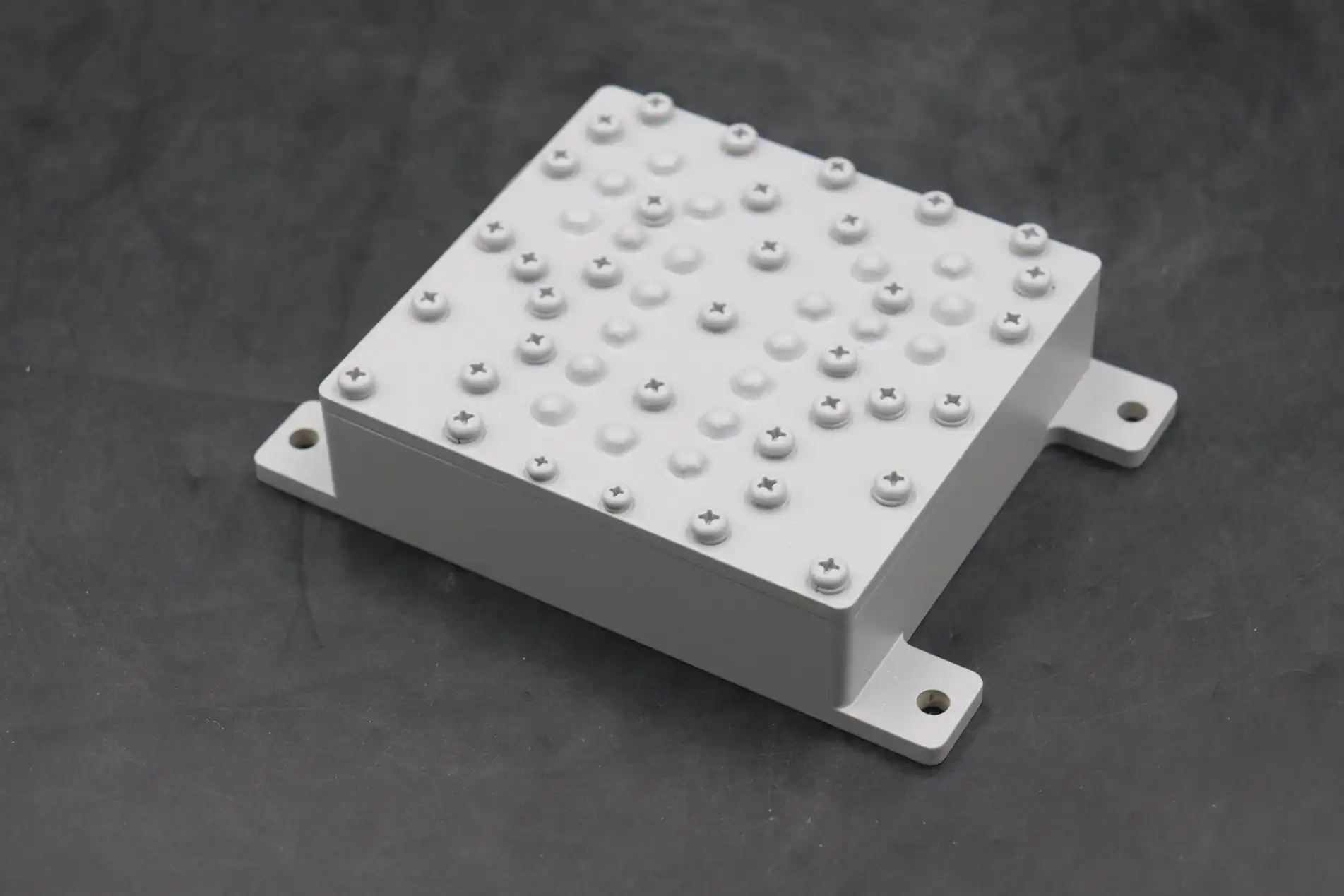
Standard RF filters usually have an insertion loss of 2 to 4 dB, which is fine for consumer devices with short ranges but not so great for long-distance telecom links or defense surveillance systems. In multi-stage RF chains, the effects add up quickly; three standard filters cascaded on top of each other cause 6–12 dB loss, which could be too much for link budgets to handle.
Quality Factor and Selectivity
The unloaded Q-factor tells you how well a filter can block close interference. Because of air dielectric and precision metalwork, low-loss coaxial filters can get Q-factors of 1,000 to 5,000, which lets them have steep skirt selectivity. This is very important in spectrum settings with a lot of channels that are only a few megahertz apart, like cellular duplexers that separate the send and receive bands.
Standard ceramic filters have Q-factors between 50 and 300, which means they have gradual roll-off characteristics. Their wider transition bands let more interference from channels next to them through, which lowers the receiver dynamic range. The "near-far problem" can be better handled by a base station with low-loss filters, which let it pick up weak mobile signals while blocking nearby high-power emitters.
Environmental Stability and Power Handling
Low-loss designs are more stable at high and low temperatures, keeping the center frequency drift below ±0.01% across a wide range of military temperature ranges. Their strong mechanical design can handle vibrations according to MIL-STD-810, which is necessary for radar systems in the air or communication systems on ships. Power ranges from watts to kilowatts, and waveguide versions can handle megawatt bursts without dielectric breakdown.
Standard filters have lower power levels and more frequency shift, which makes them less useful in high-reliability situations. Thermal cycling can change the passband characteristics, which means that the system needs to be redesigned or calibrated. These differences in performance show why aerospace and defense buyers need low-loss options even though they cost more per unit.
Practical Applications and Use Cases in B2B RF Procurement
Telecommunications Infrastructure
In order to separate the transmit and receive paths within duplexers, cellular network operators use Distributed Antenna Systems (DAS) and low loss bandpass filters in macro base stations. These filters keep transmitter noise from making receivers less sensitive, so they can work on closely spaced frequency bands at the same time. A big carrier recently said that switching from standard ceramic duplexers to low-loss coaxial designs increased coverage by 15%. This meant that fewer calls dropped and 4G/5G throughput got better.
Even stricter rules are needed for satellite ground stations. To keep from colliding with satellites nearby, uplink filters must be able to handle kilowatts of broadcast power while keeping PIM low. Our clients who run C-band and Ku-band earth stations depend on ADM's custom waveguide bandpass filters, which have been tested to 0.3 dB insertion loss to make sure that the satellite transponder gets the most effective isotropic radiated power (EIRP).
Defense and Aerospace Systems
Low-loss filters are built into military radar systems to stop harmonic signals and keep sensitive Low Noise Amplifiers (LNAs) safe from high-power jamming. X-band filters with 60 dB stopband rejection help a flying early warning radar get rid of false targets caused by transmitter leakage. Coaxial and waveguide filters are mechanically robust, so they can handle the vibrations and G-forces of an airplane while still staying calibrated during missions.
Small low loss bandpass filters are used by navigation systems, like GPS receivers in unmanned aerial vehicles (UAVs), to block out-of-band interference from things like communication radios and electronic warfare gear. These filters keep the position precision to within meters, which is very important for self-driving aircraft.
Industrial IoT and Research Institutions
Sub-6 GHz low-loss bandpass filters are being used in new industrial Internet of Things (IoT) uses to make long-range sensor networks possible in smart plants and oil refineries. Communication range is limited to hundreds of meters by standard filters' higher loss. However, optimal designs increase coverage to several kilometers, which lowers the cost of infrastructure.
University research labs that measure at high frequencies can benefit from low-loss filters that can be changed to fit the frequencies of the experiments. ADM's OEM services can make samples in just a few weeks, which helps with fast innovation processes in mmWave 5G research and signal processing for quantum computers.
Comparing Low Loss Bandpass Filters with Other Filter Types
Coaxial vs Waveguide Bandpass Filters
For frequencies below 10 GHz, coaxial bandpass filters are the best mix of size and performance. They have a much higher Q than ceramic filters while still being smaller than waveguide options. Their carefully torqued connectors and silver-plated brass housings reduce PIM, which is very important for cellular duplexers that need to meet -160 dBc PIM3 standards to avoid intermodulation distortion.
Waveguide bandpass filters work best at frequencies above 10 GHz. They use air-filled cavities to get very low insertion loss and the ability to handle kilowatts of power. When their resonant cavity designs are linked by irises, they get Chebyshev or Elliptic responses with stopband rejection of more than 80 dB. When loss limits are very small, like in satellite uplinks, radar emitters, and mmWave 5G backhaul systems, these filters are a must. Before being sent out, ADM's waveguide filters are tested on a Vector Network Analyzer (VNA) using full S-parameter sweeps to make sure they work well with modeling data.
Notch vs Bandpass Configurations
Along with low-loss bandpass filters, notch filters block certain types of interference, such as harmonic spurs and co-site emitters, by blocking them within small frequency ranges. Bandpass filters set the range of frequencies that are okay, while notch filters cut out frequencies that are bothersome. When you combine the two, you get strong front-end designs. For example, a satellite receiver might use a low-loss bandpass filter to choose the downlink band and then notch filters to get rid of radio interference from the ground.
Ceramic filters are at the cheaper end of the spectrum and work well with consumer electronics that can handle insertion loss of 3 to 5 dB. IoT modules like their small size, but professional infrastructure can't use them because they can't handle much power and have a Q-factor.
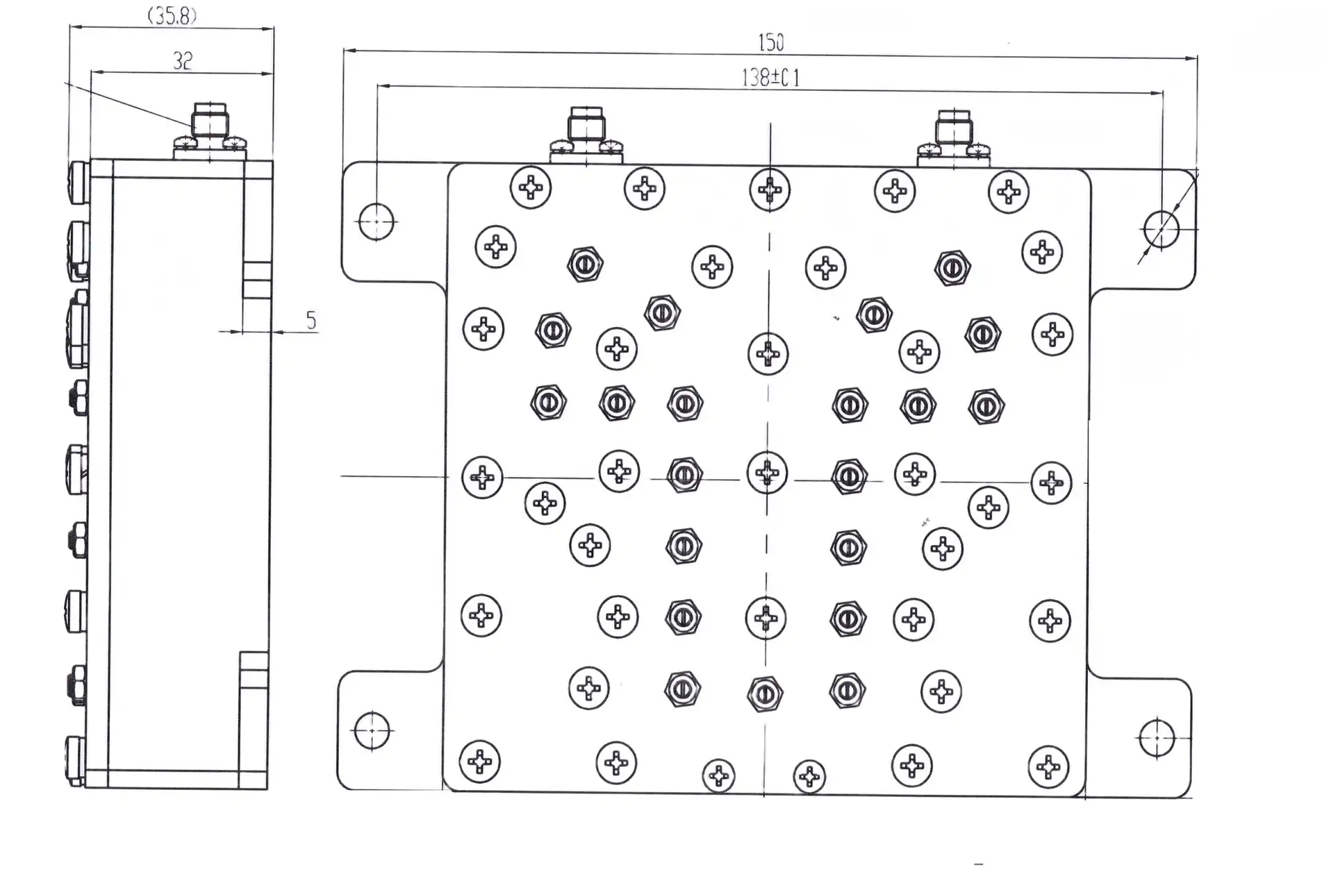
Procurement Considerations for Low Loss Bandpass Filters
Evaluating Technical Specifications
Procurement teams need to look closely at datasheets to find important factors other than insertion loss. Center frequency stability, shown in ppm/°C, shows how well the device works at different temperatures. A passband noise of less than 0.5 dB guarantees a flat gain response, which is very important for broad signals like 5G New Radio carriers. Return loss above 20 dB means that the impedance matching is good, which reduces reflections that hurt the efficiency of the transmitter.
Power handling requirements need to be carefully interpreted. In pulsed radar uses, average power numbers are different from peak power ratings. Check both CW and pulsed power limits. PIM testing according to the IEC 62037 standard confirms that the filter is suitable for use in cellular base stations, where -150 dBc PIM3 performance keeps channels from interfering with each other.
Quality Standards and Certifications
Getting ISO 9001:2015 certification means that your quality management system is strong. ADM's ISO 14001:2015 certification for the environment guarantees responsible production, and our ISO 45001:2018 certification shows our dedication to safety at work. RoHS compliance is important for European products because it gets rid of dangerous materials like mercury and lead.
Environmental Stress Screening (ESS) according to MIL-STD-202 or MIL-STD-810 is needed for military uses. ESS includes thermal shock cycles, vibration testing, and humidity exposure. Low-loss bandpass filters that pass these tests keep their tuning stable even when the field conditions are rough. Ask for test results that show Q-factor readings, X-ray Fluorescence (XRF) confirmation of plating thickness, and high-power multipaction testing for waveguide filters that are rated for vacuum.
Supplier Selection and Customization
In addition to public catalogs, elite providers offer customization options that set them apart. ADM's OEM services create filters for non-standard frequencies, specific bandwidths, and different types of connectors, helping with prototypes in aerospace and specialized telecom deployments. Our 24m microwave darkroom has antenna measurement tools that can work up to 110 GHz. This lets us fully characterize filter-antenna combined assemblies, which makes sure they work well at the system level.
Lead times range from a few days for catalog items to a few weeks for custom work. Setting up framework deals with makers makes it easier to place repeat orders and ensures predictable shipping times, which are necessary for planning production. Negotiating large orders takes advantage of economies of scale. For example, a telecom company that buys thousands of duplexers every year can get per-unit costs that are close to standard filter prices while still getting low-loss benefits.
Serialized parts and material certificates help reputable makers keep track of their products, which is very important for aerospace supply chain checks. Engage suppliers who offer technical support beyond just selling products. Help with installation, troubleshooting, and system integration is valuable throughout the lifecycles of equipment.
Conclusion
Which one you choose between standard RF filters and low loss bandpass filters depends on the performance-cost trade-offs of your application. When it comes to signal integrity, power efficiency, and environmental toughness, low-loss designs are unmatched. This is why they cost more in defense, aerospace, and telecom systems where dependability directly affects mission success. Standard filters are used in customer markets that care about price and in applications that can handle bigger losses. Procurement teams can manage budgets and improve system performance by carefully looking at insertion loss, Q-factor, environmental requirements, and supplier abilities. Because ADM has been making precise RF components for 20 years, we can help you make these important choices and make sure your systems work as well as they can.
FAQ
1. What level of insertion loss for bandpass filters is "low loss"?
Low-loss designs are filters with insertion loss less than 1.0 dB across the passband. At microwave frequencies, high-performance coaxial filters can reach as low as 0.1 to 0.3 dB, while waveguide filters can reach as low as 0.3 to 0.8 dB. Most standard filters have a range of 2 to 4 dB or more.
2. Can low-loss bandpass filters be made to work with certain frequency ranges?
Customization is one of the best things about high-end manufacturers. We often have to build filters with non-standard center frequencies, bandwidths ranging from 1% to 20% fractional bandwidth, and specific resistance needs. Within two to four weeks, prototyping services send models for review before production runs.
3. Which fields can use low-loss bandpass filters the most?
These filters are very important for radar, electronic warfare, and satellite communications, according to aerospace and defense companies. They are used by telecom companies in base stations and microwave backhaul. Custom designs are used by research institutions for spectrum experiments and measurement tools that need to be very accurate.
Partner with ADM for Superior RF Filtering Solutions
Selecting the right low loss bandpass filter provider is important for the long-term success and dependability of your system. Advanced Microwave Technologies Co., Ltd. (ADM) is an ISO 9001-certified company that has been making things for over 20 years. They have state-of-the-art test facilities, such as a 24m microwave lab that can handle frequencies up to 110 GHz. You can ask our engineering team for catalog coaxial filters for base station duplexers or custom waveguide designs for satellite ground stations. They will give you precise answers that are backed by thorough Vector Network Analyzer testing and environmental screening. Email craig@admicrowave.com right now to talk to one of our technical experts about your needs, get detailed datasheets, or look into OEM customization for your next purchase cycle.
References
1. Matthaei, G.L., Young, L., and Jones, E.M.T. (1980). Microwave Filters, Impedance-Matching Networks, and Coupling Structures. Norwood: Artech House Publishers.
2. Hong, J.S. and Lancaster, M.J. (2001). Microstrip Filters for RF/Microwave Applications. New York: John Wiley & Sons.
3. Cameron, R.J., Kudsia, C.M., and Mansour, R.R. (2007). Microwave Filters for Communication Systems: Fundamentals, Design, and Applications. Hoboken: Wiley-Interscience.
4. Levy, R. (1973). Filters with Single Transmission Zeros at Real or Imaginary Frequencies. IEEE Transactions on Microwave Theory and Techniques, Vol. 24, pp. 172-181.
5. Henoch, B. and Stracca, G.B. (2009). High Power Considerations in Passive Microwave Devices for Space Applications. European Microwave Conference Proceedings, Rome.
6. Snyder, R.V. (1999). New Application of Evanescent Mode Waveguide to Filter Design. IEEE Transactions on Microwave Theory and Techniques, Vol. 25, pp. 1013-1021.
YOU MAY LIKE
 VIEW MORELog Periodic Antenna
 VIEW MOREMicrowave Fixed Attenuator
 VIEW MORECrossguide Directional Coupler
 VIEW MOREHigh Power Waveguide Circulator
 VIEW MOREWaveguide Short Plate
 VIEW MOREDouble Ridge Waveguide Bend
 VIEW MORECoaxial Cable Connector
 VIEW MORELadder Membrane Conical Dual circular Polarization Horn Antenna
