How to Optimize Pyramidal Horn Antenna Design
Optimizing pyramidal horn antenna design requires a strategic balance of electromagnetic theory, precise geometry, and material selection. Successful optimization starts with understanding how aperture dimensions, flare angles, and waveguide transitions influence gain, beamwidth, and impedance matching. Engineers must address phase error minimization across the aperture while controlling VSWR to ensure efficient power transmission. At Advanced Microwave Technologies Co., Ltd, we've refined these principles over two decades, delivering high-performance solutions for radar, satellite communication, and EMC testing applications where reliability and precision matter most.
Understanding Pyramidal Horn Antenna Design Principles
Mastering the relationship between physical geometry and electromagnetic performance is the first step to making horn antennas work well. When procurement teams and design engineers work together on specification requirements, they have to deal with a number of interconnected factors that have a direct effect on mission-critical applications.
Aperture Size and Flare Angle Fundamentals
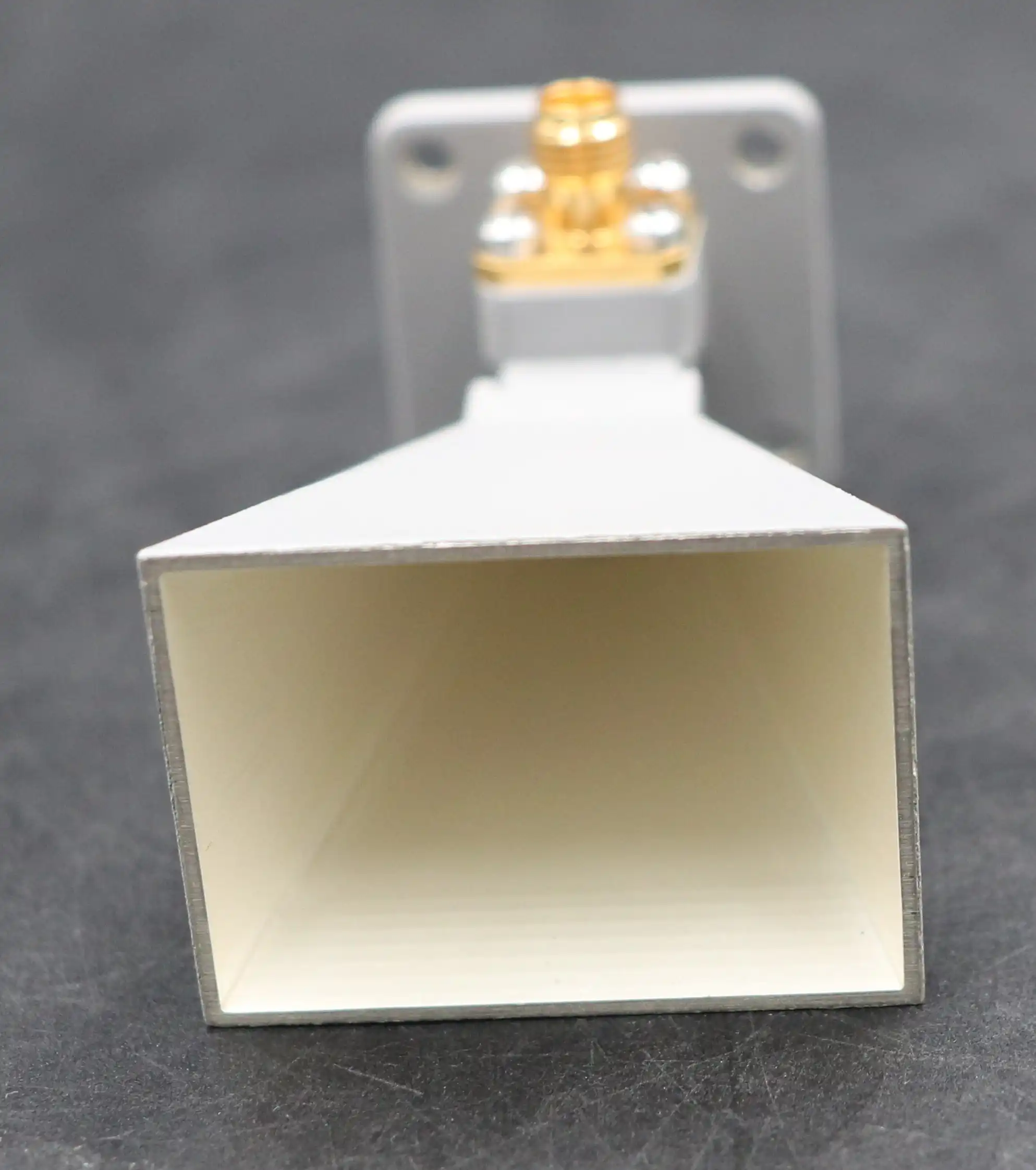
The directivity and gain of your antenna system are based on the opening measurements. Larger openings naturally give higher gain values, which can be anywhere from 10 dBi to 25 dBi based on the needs of the application. How easily the electromagnetic wave moves from the rectangular waveguide feed to empty space is controlled by the flare angle. Gradual flare angles lower phase error across the aperture, which makes the beam quality better and side-lobe levels lower. But curve lengths that are too long make production harder and cost more in materials. To find the best balance, you need to know your specific frequency range and performance goals.
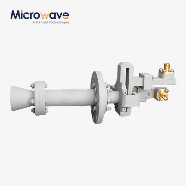
The pyramidal shape grows in both the E-plane and the H-plane, making a symmetric radiation pattern that works well for uses that need consistent coverage. This symmetry is very important when the antenna is used as a reflector feed element in radar or satellite ground stations. The controlled aperture makes sure that the parabolic reflector surface is evenly lit, which maximizes taper efficiency while minimizing spillover loss that would lower system sensitivity otherwise.
Impedance Matching and VSWR Control
One of the most difficult parts of implementing horn antennas is matching the impedance. An open-ended waveguide has low impedance, which makes signals bounce back and create standing waves that lower the efficiency of the system. In this case, the pyramidal horn structure changes the impedance gradually from the waveguide's normal impedance to the 377-ohm impedance of empty space. When built correctly, this change keeps VSWR values below 1.5:1 across the working bandwidth. This makes sure that there is little power loss and maximum signal transfer.
Wideband impedance matching is needed for many modern broadband applications, like 5G backhaul and multi-frequency radar systems. To get stable VSWR performance across octave or multi-octave bandwidths, you need to pay close attention to the design of the feed mechanism and the shape of the horn's internal parts. To avoid abrupt breaks that cause reflections, the change from the waveguide to the horn structure needs to be smooth and gradual.
Material Selection Trade-offs
Choice of material has a big effect on both how well it works electrically and how reliable it will be in the long run. For most uses, precision-machined aluminum is the best choice because it is a good mix of conductivity, mechanical strength, and weight. Chemical passivation processes, like Alodine coating, are used to keep the material from oxidizing and corroding in tough environments. Copper alloys plated with silver or gold lower skin-effect losses at high frequencies, but they cost more. These metals are used in situations where the lowest insertion loss is needed.
For defense and military uses, it's often necessary to think about more than just RF performance in pyramidal horn antenna design. Extreme changes in temperature, humidity, salt spray, and mechanical shaking must not damage the materials. When choosing materials at ADM, we make sure they meet the strict MIL-STD environmental requirements while still having the right level of tolerances for consistent electromagnetic performance. Our ISO 9001:2015-certified manufacturing processes make sure that every part meets the written requirements, from the prototype to large-scale production.
Analyzing Factors Affecting Pyramidal Horn Antenna Performance
Procurement workers can make better choices when balancing technical needs with budget limits and delivery dates when they know how different design parameters affect performance in the real world.
Wideband Versus Narrowband Design Strategies
Application needs shape design philosophy in a fundamental way. When narrowband horns are tuned to a certain frequency range, they work best at that frequency, giving them the highest gain and lowest VSWR. However, they don't work as well outside of that range. These work great for fixed-frequency radar sites or specific communication links that don't need to be able to change frequencies. On the other hand, wideband designs work well over a wider range of frequencies, so they can be used with more than one frequency and will work with future system upgrades without the need for new antennas.
For each method, the flare profile and aperture size need to be adjusted in a different way. To keep phase coherence across a wider frequency range, wideband designs usually use longer flare lengths and smoother transitions. This flexibility comes at the cost of being bigger and more difficult to make. When you tell your seller what you need, be clear about how much operational bandwidth you need so that the product they send you fits with your system design.
Electromagnetic Simulation and Virtual Prototyping
Modern antenna development relies on electromagnetic simulation software like FEKO, HFSS, and CST Microwave Studio to make sure that designs work before they are made real. These tools use numbers to solve Maxwell's equations and make very accurate predictions about radiation patterns, gain, VSWR, and other important factors. By finding design problems early in the development cycle, virtual prototyping cuts development time and costs by a huge amount.
Our engineering team at ADM uses these modeling tools along with our 24-meter radio darkroom to make sure everything is correct. Virtual modeling and physical measurements work together to make sure that products meet specifications across their entire operational range. This unified method works especially well for custom OEM projects that need solutions that are made to fit their specific performance needs. The modeling process also makes it easy to make changes quickly, so engineers can try out different designs and find the best settings before spending a lot of money on tools and production.
Radiation Pattern Interpretation and Gain Verification
Technical decision-makers can check that antenna performance meets application needs if they know how to read and understand radiation patterns. Based on its beamwidth and peak gain, the main lobe determines the main direction of highest energy. Narrower beamwidths focus energy more closely, sending more power in the direction of the target while covering less ground. Side lobes are unwanted radiation that comes from directions other than the axis and can interfere with signals or make the system less effective.
Standard gain horn antennas are used as measuring standards because their gain can be figured out theoretically from their size. During acceptance testing, predicted gain values are compared to measured values to make sure the quality of the manufacturing process. Cross-polarization isolation, which is usually higher than 25 dB in good horns, makes sure that the antenna keeps the linear polarization it's supposed to have and doesn't leak a lot of energy into the orthogonal polarization plane. When testing for EMC/EMI, these measurements are especially important because correct field generation is what determines the validity of the test and compliance with regulations.
Comparing Pyramidal Horn Antennas with Alternative Designs
When looking for the best options for different situations, procurement workers should know how pyramidal horns compare to other antenna technologies.
Performance Against Conical Horn Designs
Conical horn antennas have circular symmetry and naturally connect to circular waveguides. This means they can be used in situations that need circular polarization or axial symmetry. But pyramidal horns work really well with rectangular waveguides, which are the most common type of waveguide in microwave systems. Since the change from a rectangular waveguide to a pyramidal horn is direct, complex mode converters are not needed. This keeps the polarization pure and lowers the insertion loss.
The pyramidal shape also lets you control the E-plane and H-plane beamwidths separately, so you can make radiation patterns that fit your exact coverage needs. This adaptability is useful in radar systems that need different azimuth and elevation resolutions or in reflector feed uses where an elliptical beam shape makes the light hitting the reflector better. In addition, manufacturing factors support pyramidal shapes for many uses, since cutting rectangular shapes is easier and less expensive than cutting conical shapes, which need rotational symmetry.
Dielectric Resonator and Patch Antenna Alternatives
Dielectric resonator antennas and microstrip patch arrays have small sizes that make them useful for uses with limited room. These technologies make it possible to integrate directly onto printed circuit boards, which makes the system smaller and easier to put together. However, they usually can't compete with pyramidal horns when it comes to high gain and power handling. Horn antennas don't have any insulating materials or sensitive printed parts inside, so they can handle high levels of continuous wave power and peak pulse power that are limited mostly by air breakdown voltage.
The opening of a pyramidal horn naturally allows for more directivity than dielectric or patch elements with small electrical areas. Arrays of patch elements can get about the same gain through beamforming, but the complexity of the feed network adds to the loss and cost. The simple, passive structure of the pyramidal horn makes it very reliable, which is useful in defense and aerospace applications where a broken part could have serious effects.
Application-Specific Selection Criteria
To pick the best antenna type, you need to make sure that the technical performance matches the needs of the application and the limitations of the operation. Here are the main reasons why pyramidal horn antennas are useful in certain situations:
EMC/EMI Compliance Testing: Standard gain horns are used because their performance can be calculated and they can handle a lot of power. This is why laboratories that test for immunity and emissions according to ANSI, CISPR, or MIL-STD guidelines depend on them. The antennas make strong, focused electromagnetic fields that are needed for checking susceptibility without sending power in places it doesn't need to go. In anechoic chamber measurements, where test accuracy and consistency have a direct effect on certification results, these are the gold standards.
Satellite Ground Stations: For satellite ground stations, the pyramidal horn's even lighting makes it a perfect feed element for parabolic mirrors in the infrastructure for satellite transmission. When the apertures of the horn and reflector are properly matched, the taper works as efficiently as possible, making sure that the surface of the reflector gets even lighting without much spillover beyond the edge. This optimization directly leads to a better signal-to-noise ratio in both the uplink and downlink lines. This increases the system's capacity and link stability for sending large amounts of data quickly.
Radar Feed Networks: Modern radar systems that use phased arrays and reflectors need feed elements that work well across a wide range of operating bandwidths and can handle high amounts of transmit power. The pyramidal horn meets these needs because it is built to last and has natural broadband properties. At ADM, we've created special X-Band feed networks that give air traffic control radars very sharp beamforming. This lets them keep accurate track of airplanes even when the weather is bad and atmospheric attenuation makes system margins tight.
Procurement Insights for Pyramidal Horn Antennas
When making strategic procurement choices, it's important to weigh the needs for technical performance against business factors like cost, wait time, supplier capability, and ongoing support.
Custom Design Versus Off-the-Shelf Solutions
You can get standard catalog horns right away and at a lower cost per unit because they cover popular frequency bands and performance specs. Major suppliers keep WR-series waveguide-compatible horns in stock that cover frequency ranges from L-band to W-band. These items are good for situations where standard needs and short project timelines mean that customization isn't necessary.
When an application needs something that isn't covered by standard specifications, or when integrating a system needs special materials, mechanical connections that aren't standard, or better performance parameters, then custom-designed antennas with pyramidal horn antenna design are needed. Development partnerships with experienced manufacturers allow for co-engineering methods, in which the supplier's knowledge adds to the design resources available within the company. At ADM, our technical team works with clients from the idea stage all the way thru production. They do this by helping with electromagnetic simulations, making fast prototypes, and iterating on designs to make them work better before starting mass production.
How much it costs to go from unique solutions to standard ones depends on how big the project is and how important the technical details are. Standard products are usually better for prototyping, unless performance needs absolutely require customization. When you make more than a dozen units, you can usually afford to invest in custom tools that improve both performance and recurring manufacturing costs. Our OEM services make this process easier by providing quick prototyping for testing and review before going into full production.

Supplier Selection and Geographic Considerations
The US, Europe, and a few Asian manufacturing hubs have the most specialized production capacity for the global microwave component market. Suppliers in these areas range in how good they are at technical know-how, production capacity, quality processes, and on-time delivery. When buying things for defense or space, regulations often say that domestic suppliers or partners with the right technology transfer deals and export compliance frameworks should get priority.
When evaluating possible suppliers, you need to look at more than just the unit price. The accuracy of the machining, plating, and assembly methods used in manufacturing all have a direct effect on the quality and stability of the products they make. Quality security is shown by the fact that there are labs for measuring antenna patterns, figuring out VSWR, and making sure the power handling is correct. Quality management systems that are well-developed have certifications like ISO 9001, AS9100 for aerospace, and RoHS and REACH for environmental compliance.
With 20 years of experience making microwaves, ADM has a wide range of in-house skills and strict quality standards. We have high-tech measuring tools in our labs that can work up to 110 GHz. This lets us fully describe how antennas work at millimeter-wave frequencies. The 24-meter microwave lab has the far-field measurement lengths needed to accurately describe patterns at lower microwave frequencies. This infrastructure allows both standard product validation and custom design validation, making sure that the goods that are provided match the specs that were written down.
Cost Structures and Economies of Scale
Knowing what causes antenna costs helps people who work in procurement negotiate better and make better budget plans. The cost of materials depends on the combination chosen, the plating needed, and the state of the markets for copper, aluminum, and valuable metals. Machining gets harder as the frequency band, opening size, and tolerance standards go up. This is because higher frequencies need more precise control over dimensions. Finishing steps like passivation, plating, and protective coatings raise the cost and value of an item by making it more resistant to corrosion and better at conducting electricity.
Electromagnetic simulation, prototype fabrication, and measurement validation are examples of one-time engineering costs that come up with custom designs. These costs are spread out over a larger amount of production, which makes unit economics better for larger amounts. Specialized tooling and fixture setup costs also go down as more units are made. Using procurement strategies that combine needs and commit to fair amounts helps providers make the best use of their manufacturing resources, which can lead to lower costs while still keeping quality standards.
Implementation Strategies to Optimize Pyramidal Horn Antenna Performance
To get the best performance, you need to use organized methods for improving designs, making sure they work, and keeping an eye on the production process to make sure the finished goods meet the needs of the application.
Geometry Optimization Techniques
Making small changes to lens sizes and flare angles is the easiest way to improve efficiency. Increasing the size of the aperture increases the gain, but it also makes the lens longer and heavier. Simulation tools let you quickly look around the design space by showing amounts of gain, beamwidth, and side-lobes against geometric factors. Engineers try to find the best gain configuration that balances the error in the aperture phase with the area of the aperture, making the beam more focused without causing too much phase distortion.
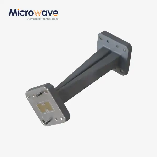
When optimizing, you should pay extra attention to the area where the waveguide feed meets the horn structure. Discontinuities that happen quickly cause reflections that lower VSWR and make radiation less effective. Transitions that happen slowly and carefully keep the impedance matching over a wider range of bandwidths. Some more advanced designs have curved curves or changes that happen in more than one step, which makes broad performance even better. These changes need to be made with great care, but they make a real difference in serious situations.
Feed Mechanism and Waveguide Interface
The general performance of an antenna is limited by the quality of the shift from waveguide to horn. The flange contact needs to be accurate in terms of its dimensions so that there are no gaps or misalignments that could cause higher-order modes or radiation leaks. Specifications for flange flatness and bolt torque keep RF seals that work reliably, which is important for consistent performance. At ADM, we carefully machine flange interfaces and include detailed assembly instructions that include the right bolt patterns and torque values to ensure a strong connection.
The size of the waveguide needs to match the frequency range that it will be used for. Each waveguide standard has a minimum frequency below which waves stop propagating and radiation stops. If you choose the right waveguide series, you can be sure that it will work with a single mode across the band you want, and you won't get large guides that let higher-order modes pass through. When it comes to interface specifications, our engineering team helps clients make sure that antenna units work with current system infrastructure.
Iterative Validation Through Testing
Even tho electromagnetic simulations are useful for making predictions, they can't be used instead of physical measurements to make sure they are correct. Antenna range testing checks the real radiating patterns, gain, and polarization properties in a controlled setting. Our 24-meter darkroom lets us do far-field measurements where the antenna's radiation pattern can fully develop. This lets us accurately describe the antenna without any near-field distortions. The Antenna Plane Near and Far Field Measuring Recombination Chamber lets you easily switch between measurement methods, so you can get detailed information about how radiation behaves across the whole operating range.
Network tester measurements show VSWR, return loss, and input impedance changes with frequency, which checks the quality of impedance matching. Power handling tests show that the antenna can handle the given peak and continuous-wave power levels without breaking down or losing its performance. Testing the temperature, humidity, and shaking of a material in its natural environment confirms that it is strong and stable. This thorough validation method makes sure that production units work consistently in real-world situations for their entire useful lives.
Conclusion
To make the best pyramidal horn antenna design, you need to know a lot about electromagnetic theory, precision manufacturing, and the needs of your specific application. A successful implementation strikes a balance between aperture geometry, impedance matching, and material choice in order to meet performance goals while staying within budget and time limits. When you compare pyramidal horns to other antenna technologies, you can see that they are better at handling high power, having predictable properties, and being easy to make for mission-critical uses. Strategic relationships with experienced makers give you access to technical tools, fast prototyping, and production methods that have been tested and proven to work. This speeds up the development process and lowers the risk of the program. Procurement teams and engineering departments can choose antenna solutions that work well in defense, aircraft, satellite communication, and industry settings by using systematic optimization techniques, iterative validation, and strict quality control.
FAQ
1. What frequency ranges are suitable for pyramidal horn antennas?
Pyramidal horn antennas work well from about 1 GHz up to millimeter-wave frequencies higher than 100 GHz. The realistic lower limit is set by the waveguide cutoff frequency. The upper limit is limited by the fact that production tolerances get harder to meet at shorter wavelengths. Common uses cover the L-band to the W-band, and certain patterns are best for normal waveguide series.
2. How do I choose between standard and custom horn antennas?
Standard stock items are easy to find and don't cost as much. They are perfect for uses that need standard specs. When you need specific frequency bands, gain patterns, non-standard mechanical connections, or performance optimization that goes beyond what's in a book, you need custom designs. The economic barrier for supporting custom development investment is based on the size and importance of the project.
3. Can pyramidal horn antennas handle high transmit power?
Because they don't have any internal dielectrics or weak parts, pyramidal horn antennas are great for high-power uses. Power handling limits are usually caused by air breakdown voltage in the waveguide feed or at the aperture. This lets continuous-wave power levels be much higher than with patch arrays or dielectric resonator antennas with the same gain.
Partner with ADM for Custom Pyramidal Horn Antenna Solutions
With more than 20 years of experience, Advanced Microwave Technologies Co., Ltd has created high-performance horn antenna designs for tough aerospace, defense, and satellite communication uses. We can do electromagnetic simulations, fast prototypes, precise manufacturing, and thorough validation tests in our state-of-the-art 24-meter microwave darkroom, which has measurement tools that can work up to 110 GHz. We are a reliable supplier of pyramidal horn antenna designs, and our quality is ISO 9001:2015 certified. We also offer quick technical support from the idea stage to production. Our OEM services cut down on the time it takes to develop new products, and our expert engineering team makes sure that your antenna systems meet all of your exact requirements for gain, VSWR, and radiation features. Get in touch with craig@admicrowave.com right away to talk about your project needs and find out how our combined design and manufacturing skills can improve the performance of your system while lowering program risks.
References
1. Balanis, Constantine A. "Antenna Theory: Analysis and Design, Fourth Edition." John Wiley & Sons, 2016.
2. Olver, A. D., Clarricoats, P. J. B., Kishk, A. A., and Shafai, L. "Microwave Horns and Feeds." IEEE Press, 1994.
3. Milligan, Thomas A. "Modern Antenna Design, Second Edition." John Wiley & Sons, 2005.
4. Stutzman, Warren L. and Thiele, Gary A. "Antenna Theory and Design, Third Edition." John Wiley & Sons, 2012.
5. Granet, Christophe and Hay, Stuart G. "Handbook of Reflector Antennas and Feed Systems Volume II: Feed Systems." Artech House, 2013.
6. Volakis, John L. "Antenna Engineering Handbook, Fourth Edition." McGraw-Hill Education, 2007.