


How to calculate the minimum bend radius for an H-bend waveguide to avoid excessive signal loss?
In microwave engineering, determining the optimal bend radius for waveguides h bend components represents a critical design consideration that directly impacts system performance and signal integrity. The calculation of minimum bend radius involves understanding the relationship between electromagnetic field distribution, waveguide geometry, and propagation characteristics within curved sections. This comprehensive analysis explores the theoretical foundations, practical methodologies, and industry standards that govern H-bend waveguide design, ensuring engineers can implement solutions that minimize insertion loss while maintaining excellent VSWR characteristics across operational frequency ranges.
The minimum bend radius for waveguides h bend configurations depends on several key parameters including operating frequency, waveguide dimensions, material properties, and acceptable loss thresholds. Generally, the minimum bend radius should be at least 2-3 times the waveguide's broad dimension to prevent excessive mode conversion and maintain single-mode propagation. Advanced Microwave Technologies Co., Ltd. incorporates these principles into their precision-engineered H-bend solutions, offering configurations from WR10 through WR430 with insertion loss specifications of ≤ 0.03 dB/cm and VSWR ≤ 1.1, ensuring optimal performance across frequencies up to 110 GHz.
Theoretical Foundation of H-Bend Radius Calculations
Electromagnetic Field Analysis in Curved Waveguides
The electromagnetic behavior within waveguides h bend sections differs significantly from straight waveguide segments due to the curvature-induced field redistribution. When electromagnetic waves propagate through curved sections, the electric and magnetic field patterns experience distortion caused by the centrifugal effect of the bend. This phenomenon creates field concentration toward the outer wall of the curve while reducing field intensity near the inner wall. The mathematical description of this behavior involves solving Maxwell's equations in curved coordinate systems, where the boundary conditions must account for the modified geometry. Advanced Microwave Technologies Co., Ltd. utilizes sophisticated electromagnetic simulation tools to analyze these field distributions, ensuring their waveguides h bend products maintain optimal field uniformity and minimize higher-order mode excitation. The company's precision engineering approach, backed by over 20 years of industry experience, incorporates advanced coating options including silver and gold plating to enhance conductivity and reduce ohmic losses. Their ISO:9001:2008 certified manufacturing processes ensure consistent performance across demanding applications in satellite communications, defense systems, and aerospace platforms where signal integrity cannot be compromised.

Mode Conversion and Propagation Characteristics
Understanding mode conversion mechanisms in waveguides h bend structures requires detailed analysis of how the fundamental TE10 mode interacts with curved boundaries. When the bend radius becomes too small relative to the waveguide dimensions, unwanted higher-order modes can be excited, leading to increased insertion loss and degraded VSWR performance. The critical radius calculation involves determining the threshold below which significant mode coupling occurs. This threshold depends on the ratio of bend radius to waveguide width, with typical industry standards recommending minimum ratios between 2:1 and 4:1 for different applications. Advanced Microwave Technologies Co., Ltd. addresses these challenges through their comprehensive product line covering frequency ranges up to 110 GHz, utilizing high-grade materials including aluminum, brass, and copper with custom material options available. Their waveguides h bend solutions incorporate flexible design configurations that support various angles and dimensions while maintaining superior signal quality through seamless transmission characteristics. The company's robust design philosophy ensures enhanced durability for demanding environments, with operating temperature ranges from -55°C to +85°C, making them suitable for aerospace and defense applications where environmental extremes are common.
Loss Mechanisms and Optimization Strategies
The primary loss mechanisms in waveguides h bend configurations include conductor losses, dielectric losses, and radiation losses, each contributing differently depending on the bend geometry and operating conditions. Conductor losses result from current flow in the metallic walls and increase with surface roughness and resistivity, while radiation losses occur when the bend radius is insufficient to maintain proper field confinement. Optimization strategies focus on balancing these competing factors to achieve minimum total loss while maintaining practical manufacturing constraints. Advanced Microwave Technologies Co., Ltd. implements comprehensive optimization methodologies in their waveguides h bend designs, incorporating advanced surface finishes and custom coatings to minimize conductor losses. Their technical expertise extends to providing design assistance and customization capabilities that cater to unique enterprise requirements, including lightweight materials for aerospace applications and corrosion-resistant options for harsh environments. The company's compliance with RoHS standards and global quality certifications ensures their products meet stringent performance requirements across diverse applications. Their OEM services include rapid prototyping capabilities that accelerate product development cycles, supported by expert technical assistance covering installation guidance and performance optimization strategies.
Practical Calculation Methods and Design Guidelines
Mathematical Formulation for Minimum Radius
The mathematical determination of minimum bend radius for waveguides h bend components involves several established formulas that correlate geometric parameters with electromagnetic performance metrics. The most commonly used approach begins with the relationship R_min = k × a, where R_min represents the minimum bend radius, k is a dimensionless factor typically ranging from 2 to 4, and a is the broad dimension of the rectangular waveguide. This simplified formula provides initial estimates, but more sophisticated calculations require consideration of frequency-dependent factors, mode coupling coefficients, and acceptable loss thresholds. Advanced empirical relationships incorporate additional terms accounting for aspect ratio effects, material properties, and manufacturing tolerances. Advanced Microwave Technologies Co., Ltd. employs comprehensive calculation methodologies that extend beyond basic formulas, utilizing their extensive laboratory facilities equipped with advanced microwave measurement equipment up to 110 GHz. Their waveguides h bend products demonstrate the practical application of these calculations, achieving insertion loss specifications of ≤ 0.03 dB/cm across their standard product line. The company's engineering team provides technical support that includes detailed performance analysis and custom configuration development, ensuring optimal results for specific application requirements. Their global export capabilities and integrated production approach enable delivery of precision-engineered solutions that meet diverse international standards and specifications.

Frequency-Dependent Considerations
The relationship between operating frequency and minimum bend radius in waveguides h bend applications exhibits complex dependencies that must be carefully analyzed for optimal performance. Higher frequencies generally require larger bend radii relative to wavelength to maintain acceptable loss levels, while lower frequencies may tolerate tighter curves without significant degradation. The frequency dependence also affects the relative importance of different loss mechanisms, with conductor losses becoming more significant at higher frequencies due to skin effect limitations. Design engineers must consider the entire operational bandwidth when specifying bend radius, ensuring adequate performance margins across the frequency range. Advanced Microwave Technologies Co., Ltd. addresses these frequency-dependent challenges through their comprehensive product portfolio spanning WR10 through WR430 waveguide sizes, each optimized for specific frequency ranges and performance requirements. Their waveguides h bend solutions incorporate advanced engineering principles that account for frequency-specific effects, supported by extensive testing and validation in their well-equipped laboratories. The company's customization capabilities enable development of solutions tailored to specific frequency requirements, including multi-octave applications where broadband performance is critical. Their technical expertise extends to providing guidance on frequency-specific optimization strategies, helping customers achieve optimal performance across diverse communication and radar applications.
Design Validation and Testing Procedures
Validation of calculated minimum bend radius values requires comprehensive testing procedures that verify both theoretical predictions and practical performance under operational conditions. Standard test methodologies include insertion loss measurements, return loss characterization, and pattern integrity analysis across the operational frequency range. Advanced testing may incorporate near-field scanning techniques to visualize field distributions and identify potential issues with mode purity or unwanted coupling effects. Environmental testing ensures performance stability across temperature ranges and mechanical stress conditions. Advanced Microwave Technologies Co., Ltd. implements rigorous validation procedures for their waveguides h bend products, utilizing state-of-the-art measurement equipment and established industry standards. Their quality control processes ensure consistent performance delivery, backed by ISO:9001:2008 certification and comprehensive documentation. The company's testing capabilities extend to custom validation procedures for specialized applications, including high-power handling verification and long-term reliability assessment. Their technical support services include performance troubleshooting and optimization guidance, helping customers validate their specific implementations and achieve target performance specifications. The integration of advanced simulation tools with practical testing enables accurate prediction of performance characteristics and efficient optimization of bend radius parameters for diverse applications.
Implementation Strategies and Industry Best Practices
Manufacturing Considerations and Tolerances
The translation of calculated minimum bend radius specifications into manufacturable waveguides h bend components requires careful consideration of production tolerances, material properties, and assembly constraints. Manufacturing processes must maintain precise dimensional accuracy while accommodating practical limitations of metalworking techniques, surface finishing operations, and quality control procedures. Tolerance analysis becomes critical when optimizing bend radius near theoretical minimums, as small dimensional variations can significantly impact electrical performance. Industry best practices emphasize the importance of statistical process control and comprehensive metrology to ensure consistent product quality. Advanced Microwave Technologies Co., Ltd. leverages over 20 years of manufacturing experience to implement sophisticated production processes that deliver precision-engineered waveguides h bend solutions. Their manufacturing capabilities encompass advanced metalworking techniques, precision machining, and specialized surface treatments including silver plating and gold plating options. The company's quality control systems ensure dimensional accuracy and electrical performance consistency across production volumes, supported by comprehensive testing and documentation procedures. Their customization services extend to material selection and specialized finishing options, enabling optimization for specific environmental conditions and performance requirements. The integration of advanced manufacturing technologies with experienced engineering expertise enables delivery of solutions that meet stringent specifications while maintaining cost-effectiveness and reliable delivery schedules.
System Integration and Performance Optimization
Successful implementation of calculated bend radius specifications requires comprehensive system-level analysis that considers the interaction between waveguides h bend components and adjacent system elements. Integration challenges may include impedance matching, mechanical alignment, thermal expansion compensation, and electromagnetic compatibility considerations. Performance optimization involves balancing competing requirements across multiple system parameters while maintaining overall reliability and cost-effectiveness. Advanced system design methodologies incorporate simulation tools, prototype testing, and iterative refinement to achieve optimal results. Advanced Microwave Technologies Co., Ltd. provides comprehensive system integration support for their waveguides h bend products, including design assistance and technical consultation services. Their engineering team works closely with customers to optimize system-level performance, addressing integration challenges and providing solutions for complex multi-component configurations. The company's OEM services extend to complete system development support, including prototype development, testing validation, and production scaling assistance. Their global supply chain capabilities and established distribution network enable efficient delivery and support for international projects. The combination of technical expertise, manufacturing capabilities, and comprehensive service offerings positions Advanced Microwave Technologies Co., Ltd. as a preferred partner for demanding microwave system applications requiring precision waveguide components.

Quality Assurance and Long-term Reliability
Long-term reliability of waveguides h bend implementations depends on comprehensive quality assurance programs that address material selection, manufacturing processes, environmental testing, and field performance monitoring. Quality systems must encompass incoming material inspection, in-process controls, final testing procedures, and post-delivery support capabilities. Reliability considerations include mechanical stability under thermal cycling, corrosion resistance in harsh environments, and electrical performance stability over extended operational periods. Industry standards provide guidelines for qualification testing and reliability assessment methodologies. Advanced Microwave Technologies Co., Ltd. implements comprehensive quality assurance programs that ensure long-term reliability of their waveguides h bend products across diverse applications. Their quality systems encompass ISO:9001:2008 certification, RoHS compliance, and adherence to international standards for microwave components. The company's testing capabilities include environmental qualification, accelerated aging studies, and comprehensive electrical characterization to validate long-term performance. Their after-sales support capabilities provide ongoing technical assistance, performance monitoring, and replacement services to ensure continued system reliability. The integration of advanced materials, precision manufacturing, and comprehensive quality systems enables delivery of waveguides h bend solutions that meet demanding reliability requirements for satellite communications, defense systems, aerospace applications, and telecommunications infrastructure where long-term performance is critical.
Conclusion
The calculation of minimum bend radius for H-bend waveguides represents a critical engineering challenge requiring comprehensive understanding of electromagnetic principles, practical manufacturing constraints, and system-level performance requirements. Success depends on integrating theoretical analysis with empirical validation, considering frequency-dependent effects, and implementing robust quality assurance procedures. Advanced Microwave Technologies Co., Ltd. demonstrates industry leadership through their precision-engineered solutions that optimize bend radius calculations while delivering superior performance across demanding applications.
Ready to optimize your waveguide system performance with precision-engineered H-bend solutions? Advanced Microwave Technologies Co., Ltd. combines over 20 years of industry expertise with advanced manufacturing capabilities to deliver customized waveguide solutions that meet your exact specifications. Our comprehensive OEM services include rapid prototyping, technical consultation, and complete system integration support, backed by our perfect supply chain system and professional R&D team. Whether you're developing next-generation satellite communication systems, defense radar applications, or aerospace navigation equipment, our expert engineers provide the technical excellence and fast delivery you need to succeed. Contact our team today at mia@admicrowave.com to discuss your specific requirements and discover how our precision waveguide solutions can enhance your system performance while meeting the most demanding technical and reliability standards.
References
1. Marcuvitz, N. "Waveguide Handbook: Radiation Laboratory Series Volume 10." Institution of Engineering and Technology, 2nd Edition, 1986.
2. Ragan, G.L. "Microwave Transmission Circuits: Radiation Laboratory Series Volume 9." McGraw-Hill Book Company, Technical Publications, 1948.
3. Collin, R.E. "Foundations for Microwave Engineering: IEEE Press Series on Electromagnetic Wave Theory." John Wiley & Sons, 2nd Edition, 2001.
4. Pozar, D.M. "Microwave Engineering: International Student Version." John Wiley & Sons, 4th Edition, 2012.
5. Balanis, C.A. "Advanced Engineering Electromagnetics: Antenna Theory Analysis and Design." John Wiley & Sons, 2nd Edition, 2012.
6. IEEE Standard 299-2006. "IEEE Standard Method for Measuring the Effectiveness of Electromagnetic Shielding Enclosures." Institute of Electrical and Electronics Engineers, 2007.
YOU MAY LIKE
 VIEW MOREWater-cooled Twist Waveguide
 VIEW MOREEnd Launch Waveguide to Coaxial Adapter
 VIEW MORERectangular Straight Waveguide
 VIEW MOREInflatable Straight Waveguide
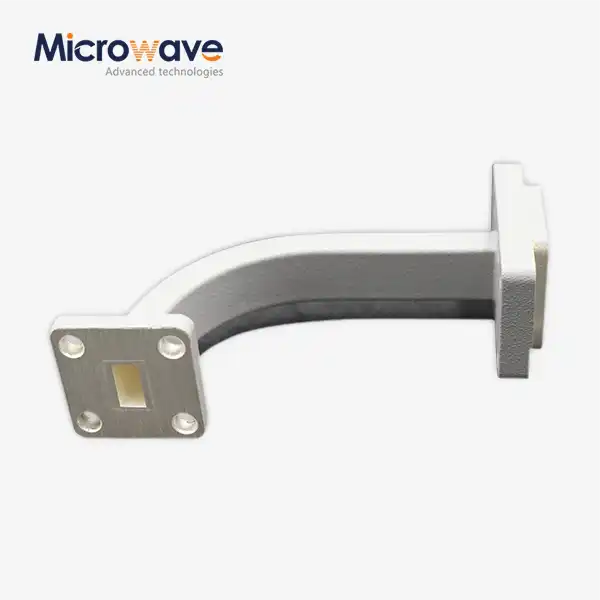 VIEW MOREWaveguide E Bend
 VIEW MOREWG Transition
 VIEW MORERight Angle Waveguide To Coaxial Adapter
 VIEW MORECircular Waveguide To Coaxial Adapter
