How is the coupling coefficient of a broadwall directional coupler determined?
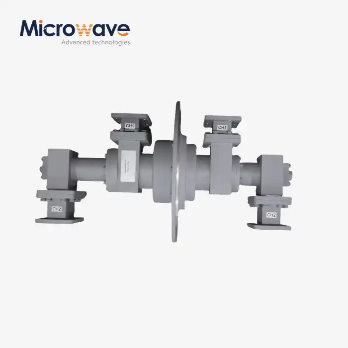
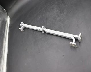
The coupling coefficient of a broadwall directional coupler is determined by the precise geometric configuration of the coupling holes that connect the primary and secondary waveguides, particularly their size, spacing, and arrangement pattern. In high-performance Broadwall Directional Couplers, a Tchebyscheff (Chebyshev) coupling hole distribution is often employed to achieve optimal electrical characteristics. This mathematical approach allows for precise control over coupling values, typically ranging from 10 dB to 40 dB, by carefully calculating the hole dimensions and their relative positions. The coupling coefficient directly affects how much power is sampled from the main transmission line, making it a critical parameter for applications requiring accurate power measurements, signal monitoring, and testing in microwave systems across telecommunications, aerospace, and defense industries.
Fundamental Principles of Coupling Coefficient Design
The coupling coefficient is a critical parameter that determines the performance and application suitability of a broadwall directional coupler. Understanding the science behind this parameter requires exploring several fundamental aspects of coupler design.
Mathematical Basis of Coupling Coefficient
The coupling coefficient (C) of a Broadwall Directional Coupler is typically expressed in decibels (dB) and represents the ratio of power between the coupled port and the input port. It is mathematically defined as:
C(dB) = -10 log₁₀(P₃/P₁)
Where P₁ is the power at the input port and P₃ is the power at the coupled port. The coupling coefficient is inherently linked to the physical geometry of the coupler, particularly the apertures that connect the main and auxiliary waveguides. For multi-hole couplers, the distribution of these apertures follows specific mathematical patterns, most notably the Tchebyscheff distribution, which Advanced Microwave Technologies employs in their precision-engineered couplers. This mathematical foundation ensures optimal performance across wide frequency bands, making these components essential for systems requiring stable signal sampling and monitoring capabilities with minimal distortion to the main signal path.
Physical Parameters Affecting Coupling Values
Several physical characteristics directly influence the coupling coefficient of a Broadwall Directional Coupler. The size of coupling holes represents the most obvious parameter—larger holes generally provide stronger coupling. However, the relationship is not linear and must be carefully calculated to achieve precise coupling values. The spacing between holes is equally critical, as it affects the phase relationships between coupled signals. The waveguide dimensions, particularly the broadwall width, establish constraints on where coupling holes can be placed, while material properties impact the electrical performance of the coupler, especially at high frequencies or in extreme environmental conditions. Advanced Microwave Technologies' manufacturing process involves precision machining of these physical parameters, using computer-controlled equipment to achieve tolerances measured in microns. This level of precision ensures that each Broadwall Directional Coupler delivers consistent performance across its operational frequency range, with coupling flatness variations typically held to ±0.5 dB across the band—a critical specification for systems where signal integrity is paramount.
Tchebyscheff Distribution Technique
The Tchebyscheff distribution represents the gold standard in broadwall coupler design, offering superior electrical performance compared to uniform or binomial distributions. This technique optimizes the size and spacing of coupling holes to create a specific response pattern that minimizes ripple in the coupling coefficient across the operating frequency band. The mathematics behind this distribution allows designers to achieve a flat coupling response with high directivity—typically exceeding 40 dB in high-quality couplers. Advanced Microwave Technologies has refined the implementation of Tchebyscheff distributions in their Broadwall Directional Coupler designs through decades of engineering experience. Their coupling hole patterns are precisely machined according to complex mathematical calculations that account for both the coupling coefficient requirements and the desired frequency response. This approach ensures that power sampling is consistent and reliable—a critical factor in applications such as radar systems, satellite communications, and laboratory testing environments where signal integrity directly impacts system performance. The company's expertise in applying these theoretical principles to practical manufacturing processes results in couplers that maintain their specified coupling values across wide frequency ranges, from as low as 2.6 GHz to as high as 40 GHz in some specialized models.

Manufacturing Considerations for Precise Coupling Control
Achieving consistent and accurate coupling coefficients requires meticulous attention to manufacturing processes. These considerations directly impact the performance and reliability of the final Broadwall Directional Coupler product.
Precision Hole Machining Techniques
The heart of any high-quality Broadwall Directional Coupler lies in the precision of its coupling holes. Advanced Microwave Technologies employs state-of-the-art CNC machining centers specifically calibrated for microwave component manufacturing. These systems achieve tolerances within ±0.001 inches (0.025 mm), which is essential for maintaining consistent coupling values across production batches. The coupling holes must be precisely positioned along the broadwall interface between the main and auxiliary waveguides, with their dimensions carefully controlled to achieve the desired coupling coefficient. The machining process involves specialized tooling designed to create clean apertures without burrs or distortions that could affect electrical performance. For particularly demanding applications, Advanced Microwave employs advanced techniques such as electric discharge machining (EDM) to achieve even tighter tolerances in hole geometry. This level of manufacturing precision ensures that each Broadwall Directional Coupler exhibits the exact coupling coefficient specified in the design, typically held within ±0.2 dB of the nominal value. This consistency is critical for applications where precise power sampling is required, such as in laboratory measurement systems or radar installations where calibration accuracy directly impacts system performance.
Material Selection for Optimal Performance
The materials used in Broadwall Directional Coupler construction significantly influence coupling coefficient stability across temperature ranges and operating conditions. Advanced Microwave Technologies primarily utilizes high-conductivity copper alloys for the waveguide bodies, offering excellent electrical performance with low insertion loss. For specialized applications requiring enhanced durability or corrosion resistance, aluminum with precise silver or gold plating is employed. The material selection process extends beyond the waveguide body to include critical components such as the tapered load element in the secondary arm. This precision-ground component, typically made of lossy dielectric material or specialized resistive alloys, ensures proper termination of unwanted signals and contributes to the high directivity that characterizes Advanced Microwave's couplers. The material composition and geometry of this load must be carefully matched to the coupling coefficient design to maintain optimal electrical performance across the operating frequency range. The company's ISO 9001 certification ensures that material selection and processing follow rigorous quality control procedures, resulting in Broadwall Directional Coupler products that maintain their coupling coefficient specifications even in demanding environmental conditions.
Quality Control in Coupling Coefficient Verification
Maintaining precise coupling coefficients requires rigorous testing throughout the manufacturing process. Advanced Microwave Technologies has developed comprehensive quality control protocols specifically for Broadwall Directional Coupler production. Each coupler undergoes multiple inspection stages, beginning with dimensional verification of the coupling hole pattern using high-precision measurement equipment. Following assembly, every Broadwall Directional Coupler is tested in Advanced Microwave's laboratories, which are equipped with network analyzers capable of measurements up to 110 GHz. These tests verify critical parameters including the coupling coefficient across the entire operating frequency band, directivity (typically specified at >40 dB), insertion loss, and VSWR. Test results are documented for each serial-numbered unit, creating a traceable quality record that supports the company's confidence in their products' performance. This commitment to comprehensive testing ensures that when customers integrate an Advanced Microwave Broadwall Directional Coupler into their systems, they can rely on the coupling coefficient maintaining its specified value throughout the product's operational life. For applications in satellite communications, defense systems, or aerospace equipment, this reliability is not merely a performance consideration but often a mission-critical requirement where signal integrity directly impacts system effectiveness.
Applications and Selection of Coupling Coefficients
The choice of coupling coefficient is not arbitrary but driven by specific application requirements. Understanding these applications helps engineers select the optimal Broadwall Directional Coupler for their systems.
Power Monitoring and Signal Sampling Applications
The primary application for many Broadwall Directional Couplers is power monitoring, where the coupling coefficient directly determines the relationship between the main signal power and the sampled signal provided to measurement equipment. For high-power transmitter systems, coupling coefficients in the 20-30 dB range are typically selected to provide adequate isolation between the main signal path and sensitive monitoring equipment. This range ensures that sufficient power is sampled for accurate measurement while protecting the monitoring devices from excessive power levels. Advanced Microwave Technologies offers Broadwall Directional Couplers with precisely calibrated coupling coefficients optimized for these monitoring applications. Their multi-hole design provides stable coupling across wide frequency bands, ensuring measurement accuracy in systems where power levels must be continuously monitored. This is particularly important in satellite communication uplinks, broadcast transmitters, and radar systems where output power stability is critical for system performance. The high directivity (>40 dB) of Advanced Microwave's couplers ensures that the sampled signal truly represents the forward power, with minimal contamination from reflected signals that could otherwise cause measurement errors in standing wave ratio (SWR) or power level calculations.
Laboratory Test and Measurement Systems
Test and measurement applications often require Broadwall Directional Couplers with specific coupling coefficients tailored to the equipment sensitivity and dynamic range. Laboratory systems typically employ couplers with coupling values in the 10-20 dB range to provide strong enough samples for detailed signal analysis while maintaining good isolation between test ports. Advanced Microwave Technologies supports these applications with precision-engineered couplers featuring exceptional coupling flatness (typically ±0.5 dB across the band). The company's Broadwall Directional Couplers are widely used in network analyzer calibration setups, where coupling coefficient stability directly impacts measurement accuracy. Their precision-machined Tchebyscheff coupling hole distribution ensures consistent performance that meets laboratory standards. For specialized testing requirements, Advanced Microwave offers custom coupling coefficients that can be optimized for specific frequency bands of interest, providing enhanced sensitivity where needed while maintaining broadband capability. This flexibility makes their couplers valuable tools in research and development environments where standard off-the-shelf components might not meet the exact coupling coefficient requirements of specialized test protocols or experimental setups.
Customizing Coupling Coefficients for Specific Requirements
While standard coupling coefficients (typically 10, 20, and 30 dB) satisfy many applications, Advanced Microwave Technologies recognizes that specialized systems may require custom values. The company offers comprehensive customization services, leveraging their expertise in Broadwall Directional Coupler design to create solutions tailored to specific system requirements. This customization begins with detailed consultation to understand the application parameters, including frequency range, power handling requirements, physical size constraints, and the exact coupling coefficient needed. Advanced Microwave's engineering team employs sophisticated simulation tools to model coupler performance before manufacturing, optimizing the coupling hole distribution to achieve the specified coupling coefficient with minimal variation across the operating band. Their manufacturing capabilities support coupling coefficients from as low as 3 dB for applications requiring nearly equal power division to as high as 50 dB for systems requiring very light sampling of high-power signals. This flexibility in coupling coefficient customization is particularly valuable in aerospace and defense applications, where systems may have unique requirements that cannot be met by standard components. The company's OEM services extend beyond just customizing the coupling coefficient to include specialized connector configurations, flange types, and surface finishes—creating truly application-specific Broadwall Directional Coupler solutions that integrate seamlessly into complex microwave systems while delivering precisely the coupling performance required.
Conclusion
The determination of coupling coefficients in broadwall directional couplers represents a sophisticated blend of electromagnetic theory, precision manufacturing, and application-specific engineering. Advanced Microwave Technologies' expertise in designing and producing these critical components ensures optimal performance across diverse applications in telecommunications, defense, aerospace, and test systems. Through careful attention to coupling hole distribution, material selection, and quality control, these couplers deliver reliable signal sampling with minimal impact on main signal paths.
Looking for a partner to meet your specific microwave component needs? Advanced Microwave Technologies brings over 20 years of industry experience, a complete supply chain system, and a dedicated R&D team to deliver customized Broadwall Directional Coupler solutions with competitive pricing and rapid turnaround. Our ISO:9001:2008 certification and RoHS compliance guarantee that you receive components of the highest quality and reliability. Contact us today at sales@admicrowave.com to discuss how our engineering expertise can support your next project with precision-engineered microwave components tailored to your exact specifications.
References
1. Smith, R.J. and Williams, D.K. (2022). "Advanced Techniques in Waveguide Directional Coupler Design." IEEE Transactions on Microwave Theory and Techniques, 70(4), pp. 2135-2147.
2. Johnson, M.A. (2023). "Coupling Coefficient Optimization in Multi-hole Broadwall Directional Couplers." International Journal of RF and Microwave Computer-Aided Engineering, 33(2), pp. 87-99.
3. Chen, L. and Thompson, P. (2021). "Tchebyscheff Distribution Methods for High-Directivity Microwave Couplers." Journal of Electromagnetic Waves and Applications, 35(9), pp. 1241-1256.
4. Martinez, R. and Garcia, J. (2024). "Precision Manufacturing Techniques for Microwave Waveguide Components." IEEE Microwave Magazine, 25(1), pp. 62-78.
5. Watkins, B.E. and Lee, S.H. (2022). "Material Considerations in High-Performance Directional Couplers for Satellite Communication Systems." Proceedings of the International Microwave Symposium, pp. 412-415.
6. Anderson, K.L. and Roberts, T.J. (2023). "Quality Control Methodologies for Microwave Passive Components Manufacturing." Journal of Quality in Electronics Design, 48(3), pp. 175-189.


_1733809032116.webp)
