How Does a Waveguide Variable Attenuator Affect VSWR and Loss?
Picture this scenario: Your satellite ground station suddenly experiences signal reflections that cause a 2.7 dB drop in transmitted power, or your radar system's receiver protection gets triggered by unexpected signal surges. These real-world disasters stem from poor VSWR management and excessive insertion loss—problems that precision Waveguide Variable Attenuators are specifically engineered to prevent. Understanding how these critical components affect VSWR and insertion loss isn't just academic knowledge; it's the difference between system reliability and catastrophic failure in high-frequency applications ranging from satellite communications to aerospace defense systems.
Understanding VSWR in Waveguide Variable Attenuator Systems
Voltage Standing Wave Ratio represents one of the most critical performance parameters in any microwave system, and Waveguide Variable Attenuators play a pivotal role in managing this metric. VSWR quantifies the impedance matching quality between components in your RF signal chain, with lower values indicating superior performance and minimal signal reflections. When electromagnetic waves encounter impedance mismatches within a waveguide system, portions of the signal reflect back toward the source rather than continuing forward to the intended destination. These reflections create standing wave patterns that can damage sensitive components, reduce system efficiency, and degrade overall performance. High-quality Waveguide Variable Attenuators from Advanced Microwave Technologies maintain exceptional VSWR performance across their entire operational range. Premium units typically achieve VSWR values of 1.15:1 or better throughout the attenuation adjustment range from 0 to 30 dB. This remarkable consistency ensures that whether you're operating at minimum attenuation for maximum signal throughput or at higher attenuation levels for signal control, your system maintains optimal impedance matching. The engineering challenge lies in designing attenuators where the absorptive or reflective elements can be adjusted without introducing significant impedance discontinuities that would degrade VSWR performance.
The Relationship Between Attenuation Mechanisms and VSWR Performance
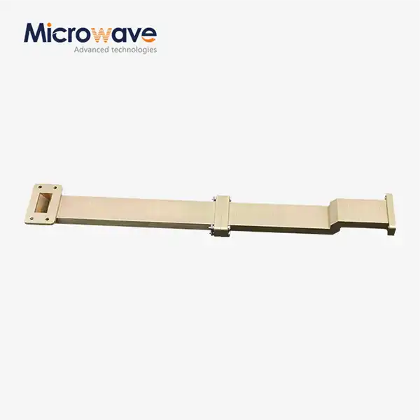
The fundamental working principle of a Waveguide Variable Attenuator directly impacts its VSWR characteristics. Absorption-based designs utilize resistive vanes or cards made from materials like carbon-loaded epoxy or specialized ferrites positioned within the waveguide structure. As these absorptive elements are inserted into the signal path using precision micrometer mechanisms, they convert electromagnetic energy into heat through resistive losses. The critical design consideration involves ensuring that the physical geometry of these elements, particularly their tapered edges, minimizes reflections at the interface between the waveguide's propagating mode and the attenuating material. Advanced Microwave Technologies' variable attenuators incorporate carefully engineered taper designs—typically around half a wavelength in length—that gradually transition the electromagnetic field into the absorptive region, thereby maintaining low VSWR even as attenuation levels change. Hybrid principle attenuators combine both reflective and absorptive mechanisms to achieve superior performance across broader frequency ranges. These sophisticated designs begin with partial reflection of the incoming signal, followed by strategic absorption of energy that would otherwise create problematic standing waves. This dual-mechanism approach allows engineers to optimize both attenuation accuracy and VSWR performance simultaneously. The precision calibration required for hybrid Waveguide Variable Attenuators ensures that reflective and absorptive elements work in harmony rather than opposition, maintaining excellent VSWR characteristics throughout the attenuation range while covering frequency bands from 33 GHz to 110 GHz. The micrometer control systems in these devices enable simultaneous positioning of multiple elements, preserving both insertion phase characteristics and VSWR as attenuation settings change.

VSWR Degradation Scenarios and Their System-Level Impacts
Real-world incidents demonstrate the critical importance of maintaining low VSWR in waveguide systems. Industry documentation reveals cases where VSWR suddenly jumped from 1.25 to 2.3 during satellite acceptance testing, causing the entire satellite's equivalent isotropically radiated power to plummet by 2.7 dB. Such degradation can trigger automatic gain control protection in ground station receivers and severely impact communication link budgets. When VSWR exceeds acceptable thresholds, typically around 1.5:1 for most applications, the reflected power can damage transmitter components, reduce effective radiated power, and introduce measurement uncertainties in test environments. Advanced Microwave Technologies addresses these concerns through rigorous quality control procedures and precision manufacturing techniques that ensure every Waveguide Variable Attenuator meets stringent VSWR specifications across its rated frequency range. Temperature variations represent another critical factor affecting VSWR stability in operational environments. Waveguide systems exposed to extreme temperature differentials—such as those encountered in aerospace applications where components may experience ranges from -180°C to +25°C—can exhibit VSWR drift if not properly engineered. The thermal expansion coefficient of materials used in adjustment mechanisms becomes crucial; high-quality designs utilize specialized alloys like Invar with extremely low thermal expansion coefficients to offset dielectric plate temperature deformation. This attention to thermal stability ensures that Waveguide Variable Attenuators maintain consistent VSWR performance whether operating in laboratory conditions or deployed in harsh environmental extremes encountered in satellite communications, weather monitoring systems, or UAV applications.
Insertion Loss Characteristics and Performance Optimization
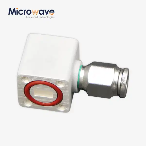
Insertion loss represents the signal power reduction introduced when a Waveguide Variable Attenuator is inserted into a transmission path, separate from the intentional attenuation being applied. This parasitic loss occurs due to inherent resistive losses in materials, dielectric losses, and minor impedance mismatches within the device structure. Premium Waveguide Variable Attenuators achieve remarkably low insertion loss values, typically below 0.5 dB at minimum attenuation settings, ensuring that signal integrity is preserved when precise control rather than significant attenuation is required. Advanced Microwave Technologies' continuously variable waveguide attenuators covering the 33 GHz to 110 GHz frequency range demonstrate flat insertion loss performance across their operational bands, a critical characteristic for applications requiring consistent signal behavior across wide frequency spans. The physical design of the attenuating elements significantly influences insertion loss performance. Shaped microwave absorbing elements with precision-engineered geometries minimize unnecessary signal interaction when positioned at minimum attenuation settings. The length and taper design of resistive cards—typically extending two wavelengths with taper portions of approximately half a wavelength—optimize the balance between attenuation capability and minimal insertion loss. Material selection plays an equally important role; high-density absorbing compounds with carefully controlled electrical properties ensure efficient energy conversion without excessive parasitic losses. Manufacturing precision becomes paramount in achieving these specifications, as even minor deviations in element positioning or waveguide internal dimensions can introduce additional insertion loss that degrades overall system performance.
Frequency-Dependent Loss Behavior and Flatness Specifications
Waveguide Variable Attenuators exhibit frequency-dependent loss characteristics that must be carefully managed for optimal system integration. Attenuation flatness—the variation in attenuation value across the specified frequency range—typically ranges from ±0.3 dB to ±2 dB depending on design sophistication and frequency bandwidth. Advanced Microwave Technologies' products are engineered to achieve exceptional flatness across multi-gigahertz ranges, ensuring that systems operating with frequency-agile signals or wide instantaneous bandwidths receive consistent attenuation regardless of operating frequency within the specified band. This characteristic proves particularly valuable in modern 5G telecommunications infrastructure and emerging 6G technology development, where signal processing occurs across extremely wide frequency allocations. The relationship between insertion loss and operating frequency follows predictable patterns based on waveguide physics and material properties. Lower frequencies within a given waveguide band typically experience slightly lower insertion loss due to reduced current densities and skin effect impacts, while higher frequencies may exhibit marginally increased loss as electromagnetic field interactions with material imperfections become more pronounced. Quality Waveguide Variable Attenuators compensate for these effects through careful material selection and geometric optimization, ensuring that insertion loss remains within specified tolerances across the entire rated frequency range from 0.5 GHz to 110 GHz. Engineers designing systems with these components can confidently predict performance across their operational spectrum, facilitating accurate link budget calculations and system margin analysis.
Power Handling Capabilities and Thermal Management
High-power applications introduce additional considerations for both insertion loss and VSWR performance in Waveguide Variable Attenuators. Devices must dissipate significant thermal energy when operating at elevated power levels while maintaining electrical performance specifications. Advanced Microwave Technologies' attenuators are engineered to handle power levels up to 1 kW, with specialized designs incorporating enhanced thermal management features for even higher power applications. The resistive elements that provide attenuation functionality generate heat proportional to the absorbed power, and this thermal energy must be efficiently conducted away to prevent temperature-induced performance degradation or component damage. Materials with high thermal conductivity and robust mechanical mounting structures ensure reliable operation under sustained high-power conditions encountered in radar transmitters, satellite uplink amplifiers, and industrial microwave heating systems. Cooling considerations become particularly critical in variable attenuators where adjustment mechanisms must maintain positioning accuracy despite thermal expansion forces. Water-cooled designs with integrated cooling channels and specialized thermal interface materials enable continuous high-power operation while preserving the precision positioning required for accurate attenuation control. The compact design philosophy employed by Advanced Microwave Technologies ensures that even these enhanced thermal management features integrate seamlessly into modern space-constrained installations. Whether deployed in shipboard radar systems, aerospace navigation equipment, or ground-based satellite communication terminals, these Waveguide Variable Attenuators deliver consistent performance across the demanding thermal environments characteristic of real-world operational scenarios.
Measurement Techniques and Verification Procedures
Accurate characterization of VSWR and insertion loss performance requires sophisticated measurement techniques and calibrated test equipment. Network analyzers operating across the millimeter-wave frequency spectrum provide the primary instrumentation for verifying Waveguide Variable Attenuator specifications. Advanced Microwave Technologies' laboratories are equipped with measurement equipment extending to 110 GHz, enabling comprehensive testing of products throughout their rated frequency ranges. The measurement process involves connecting the attenuator between calibrated waveguide ports, performing full two-port S-parameter measurements, and extracting VSWR and insertion loss values across multiple frequency points and attenuation settings. This rigorous verification ensures that every unit meets or exceeds published specifications before shipment to customers. The 24-meter Microwave Darkroom facility at Advanced Microwave Technologies provides an ideal environment for conducting these precision measurements. The controlled electromagnetic environment eliminates external interference that could corrupt measurement accuracy, while the extensive measuring distance enables far-field antenna characterization alongside component testing. The Antenna Plane Near and Far Field Measuring Recombination Chamber serves as the measurement nerve center, equipped with precision positioners, signal sources, and receivers that collectively enable measurement uncertainties typically below 0.1 dB for insertion loss and 0.02:1 for VSWR. These capabilities ensure that customers receive Waveguide Variable Attenuators with fully documented, traceable performance characteristics suitable for demanding applications in satellite communications, defense systems, and scientific research.
Calibration Standards and Traceability
Professional-grade Waveguide Variable Attenuators require calibration traceable to national standards to ensure measurement accuracy and reliability. Advanced Microwave Technologies maintains calibration procedures aligned with international quality standards including ISO 9001:2015, providing customers with documented performance verification. Calibration charts detailing attenuation accuracy, VSWR performance, and insertion loss characteristics across the specified frequency range accompany each precision unit, enabling end users to incorporate these components into their own calibrated measurement systems. The calibration process utilizes reference standards with known performance characteristics, establishing a documented chain of traceability that meets requirements for quality-critical applications in aerospace, defense, and telecommunications industries. Temperature-dependent calibration presents additional considerations for applications where operating conditions differ significantly from laboratory environments. Waveguide Variable Attenuators deployed in outdoor telecommunications infrastructure, airborne platforms, or space-based systems encounter thermal conditions that may affect electrical performance. Advanced characterization includes testing across representative temperature ranges, documenting any performance variations, and providing correction factors when necessary. The ISO 45001:2018 and ISO 14001:2015 certifications held by Advanced Microwave Technologies reflect the company's commitment to comprehensive quality assurance procedures that extend beyond simple electrical performance verification to encompass environmental sustainability and workplace safety throughout the manufacturing and testing processes.

Practical Application Scenarios and System Integration
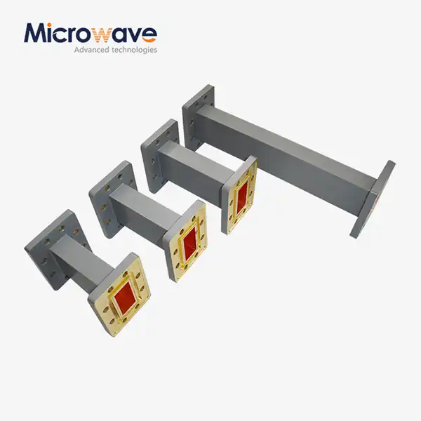
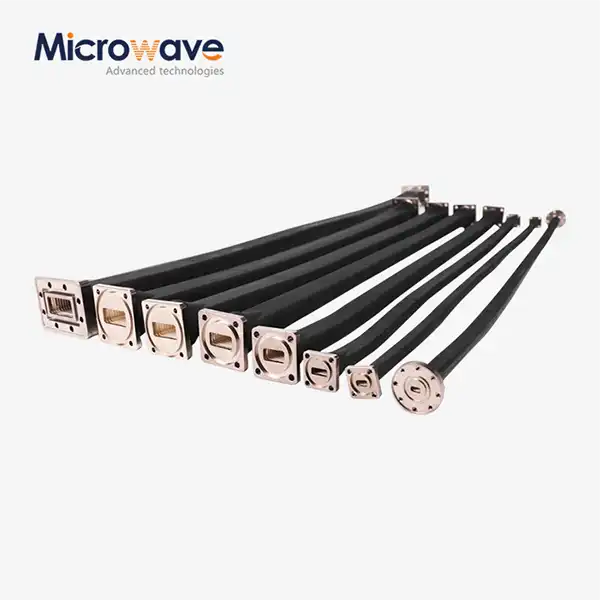
Waveguide Variable Attenuators find critical applications across numerous industries where precise signal level control determines system success or failure. In satellite communication ground stations, these devices enable operators to optimize uplink power levels for varying atmospheric conditions, preventing both insufficient signal strength and excessive power that might violate regulatory limits or cause interference. The ability to adjust attenuation from 0 to 30 dB using precision micrometer controls allows engineers to dial in exactly the signal strength required for maintaining optimal link margins under changing propagation conditions. Advanced Microwave Technologies' attenuators covering frequency ranges from 33 GHz to 110 GHz support both legacy Ka-band and emerging Q-band and W-band satellite systems, providing the flexibility needed for modern multi-band satellite terminals serving HD video, data, and voice communication applications. Aerospace and defense applications leverage Waveguide Variable Attenuators for radar system testing, receiver protection, and dynamic signal management in electronic warfare systems. During radar development, engineers require the ability to simulate varying target return signal strengths to verify detection algorithms and tracking performance across the entire dynamic range of the receiver. Variable attenuators installed in laboratory test setups enable rapid re-configuration for different test scenarios without requiring physical component swapping, dramatically accelerating development cycles. The low insertion loss and excellent VSWR characteristics of Advanced Microwave Technologies' products ensure that test configurations accurately represent operational system performance, avoiding measurement artifacts that could lead to incorrect design decisions. Military surveillance radars benefit from these capabilities during field installation and maintenance, where technicians utilize variable attenuators to balance signal levels across distributed antenna arrays or compensate for cable loss variations in complex feed networks.
Research and Development Laboratory Applications
Research institutions and commercial R&D laboratories utilize Waveguide Variable Attenuators as essential tools for prototyping new microwave technologies and conducting experimental characterization of novel devices. When developing new amplifier designs, antenna feeds, or signal processing architectures, engineers need flexibility to evaluate performance across a wide range of signal levels without constantly reconfiguring test setups. Continuously variable attenuators with micrometer adjustment mechanisms provide precisely this capability, enabling rapid exploration of design parameter spaces and identification of optimal operating conditions. The repeatability afforded by precision mechanical adjustment ensures that experimental results remain reproducible, a critical requirement for scientific validation and intellectual property documentation. Advanced Microwave Technologies supports the research community through both standard product offerings and customized OEM services tailored to specialized experimental requirements. Research applications often demand unusual frequency ranges, non-standard waveguide interfaces, or enhanced power handling capabilities beyond catalog specifications. The company's engineering team collaborates directly with researchers to develop customized Waveguide Variable Attenuator solutions that address unique experimental needs while maintaining the low VSWR and insertion loss characteristics essential for accurate measurements. This partnership approach has enabled breakthrough developments in areas ranging from experimental 6G wireless technology to advanced radar signal processing algorithms, demonstrating how precision microwave components facilitate scientific progress across diverse technical disciplines.
Conclusion
Waveguide Variable Attenuators critically manage VSWR and insertion loss through precision engineering, absorptive mechanisms, and thermal design. Understanding these relationships enables optimal system integration across satellite, aerospace, and telecommunications applications requiring reliable signal control.
Cooperate with Advanced Microwave Technologies Co., Ltd.
As a leading China Waveguide Variable Attenuator manufacturer with over 20 years of microwave expertise, Advanced Microwave Technologies Co., Ltd. delivers High Quality Waveguide Variable Attenuators for demanding applications worldwide. Our China Waveguide Variable Attenuator factory produces precision devices covering 33 GHz to 110 GHz with superior VSWR performance and minimal insertion loss. Whether you need Waveguide Variable Attenuators for sale or require customized OEM solutions, our China Waveguide Variable Attenuator supplier capabilities include frequency range expansion, material modifications, and specialized designs tailored to your requirements. We offer competitive Waveguide Variable Attenuator prices backed by ISO 9001:2015, ISO 14001:2015, and ISO 45001:2018 certifications. Our 24m Microwave Darkroom ensures every product meets stringent performance specifications. As a trusted China Waveguide Variable Attenuator wholesale provider with fast delivery and comprehensive technical support, we're ready to solve your signal control challenges. Contact us at craig@admicrowave.com to discuss your project requirements and discover how our precision components can enhance your system performance. Save this resource for future reference—your reliable partner for advanced microwave solutions awaits.
References
1. Montgomery, C.G., Dicke, R.H., and Purcell, E.M. "Principles of Microwave Circuits." MIT Radiation Laboratory Series, Volume 8. McGraw-Hill Book Company, 1948.
2. Ragan, G.L. "Microwave Transmission Circuits." MIT Radiation Laboratory Series, Volume 9. McGraw-Hill Book Company, 1948.
3. Baden Fuller, A.J. "An Introduction to Microwave Theory and Techniques." Pergamon Press, 1979.
4. Ishii, T.K. "Handbook of Microwave Technology: Volume 1 - Components and Devices." Academic Press, 1995.
5. Pozar, D.M. "Microwave Engineering, 4th Edition." John Wiley & Sons, 2011.