Get Custom Waveguide Power Dividers Tailored for Your Unique Application Needs
In today's demanding high-frequency communication landscape, engineers face a critical challenge: achieving precise power distribution while maintaining signal integrity across complex microwave systems. When your satellite ground station experiences signal degradation, your radar system fails to detect targets accurately, or your aerospace defense application demands flawless performance in harsh environments, the solution lies in selecting the right Waveguide Power Divider. These specialized components serve as the backbone of modern RF systems, enabling reliable power splitting across multiple paths with minimal insertion loss and maximum isolation. This comprehensive guide addresses the specific needs of engineers working with frequencies from 2 GHz to 110 GHz, providing insights into custom solutions that ensure your applications achieve optimal performance standards.
Understanding Waveguide Power Divider Technology and Applications
The Waveguide Power Divider represents one of the most critical components in high-frequency microwave systems, serving as the essential link that enables efficient power distribution across multiple signal paths. These sophisticated devices operate by utilizing the electromagnetic properties of hollow metallic structures to guide and split microwave energy with exceptional precision. In satellite communications, radar systems, and aerospace applications, the reliability of a Waveguide Power Divider directly impacts overall system performance, making proper selection and customization paramount for mission-critical operations. Modern Waveguide Power Divider designs incorporate advanced electromagnetic modeling techniques to minimize insertion loss while maximizing isolation between output ports. The fundamental principle relies on carefully engineered junction geometries that maintain impedance matching across the specified frequency range. Engineers working with these components must consider factors such as power handling capabilities, VSWR performance, and environmental operating conditions when specifying requirements for their particular applications.
Key Performance Parameters for Custom Solutions
When developing custom Waveguide Power Divider solutions, several critical performance parameters must be carefully balanced to meet specific application requirements. Insertion loss characteristics directly impact system efficiency, with typical specifications requiring less than 0.5 dB loss across the operating bandwidth. Power handling capabilities become crucial in high-power applications, where thermal management and material selection play vital roles in ensuring reliable long-term operation under demanding conditions. Isolation performance between output ports represents another fundamental specification that affects overall system performance. Superior isolation, typically exceeding 20 dB, ensures that signals do not interfere with each other, maintaining clear and stable transmission characteristics essential for precision applications. The VSWR specification, commonly maintained below 1.5, indicates how well the component matches the characteristic impedance of the connected waveguide system, directly affecting signal reflection and overall efficiency.

Material Selection and Manufacturing Considerations
The choice of materials for Waveguide Power Divider construction significantly influences both performance characteristics and environmental durability. Aluminum alloys provide excellent conductivity while offering lightweight construction suitable for aerospace applications where weight constraints are paramount. Brass materials deliver superior conductivity and corrosion resistance, making them ideal for marine and harsh environment applications. Copper construction offers the highest conductivity but requires careful consideration of weight and cost factors in system design. Manufacturing precision plays a crucial role in achieving specified performance parameters, particularly for high-frequency applications where dimensional tolerances directly impact electromagnetic behavior. Advanced CNC machining techniques ensure consistent wall thickness and surface finish quality, while precise junction geometries maintain impedance matching across the entire frequency range. Quality control procedures, including network analyzer testing and environmental stress screening, verify that each Waveguide Power Divider meets stringent performance specifications before delivery to customers.
Custom Waveguide Power Divider Design Solutions
The development of custom Waveguide Power Divider solutions requires a comprehensive understanding of electromagnetic theory combined with practical manufacturing constraints and application-specific requirements. Engineers must carefully balance competing design objectives such as bandwidth, size, power handling, and environmental resistance to create optimal solutions for their particular applications. The customization process begins with detailed analysis of system requirements, including frequency range, power levels, environmental conditions, and physical constraints that influence the final design approach. Advanced electromagnetic simulation tools enable precise prediction of device performance before physical prototyping, reducing development time and ensuring first-pass design success. These sophisticated modeling capabilities allow engineers to optimize junction geometries, predict insertion loss characteristics, and analyze isolation performance across the entire frequency spectrum. The iterative design process incorporates both electromagnetic optimization and thermal analysis to ensure reliable operation under specified power levels and environmental conditions.
Waveguide Size Selection and Frequency Range Optimization
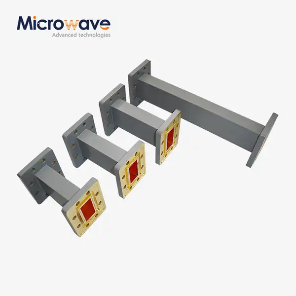
The selection of appropriate waveguide sizes for custom Waveguide Power Divider applications requires careful consideration of frequency range, power handling requirements, and physical constraints within the overall system design. Standard waveguide sizes such as WR-90, WR-51, WR-34, WR-28, and WR-22 each offer specific advantages for different frequency ranges and power levels. WR-90 waveguides provide excellent power handling capabilities for X-band applications, while smaller sizes like WR-22 enable compact designs for millimeter-wave frequencies approaching 110 GHz. Frequency range optimization involves careful analysis of cutoff frequencies, single-mode operation bandwidth, and higher-order mode suppression characteristics. Custom designs may incorporate non-standard waveguide dimensions to achieve specific bandwidth requirements or to accommodate unusual physical constraints within the host system. The relationship between waveguide dimensions and electromagnetic propagation characteristics requires precise calculation to ensure optimal performance across the entire operating frequency range.
Advanced Customization Features and Capabilities
Modern Waveguide Power Divider customization capabilities extend far beyond basic frequency and power specifications, encompassing sophisticated features tailored to specific application requirements. Variable power division ratios allow engineers to distribute power unequally among output ports, enabling optimized system architectures for complex antenna arrays or multi-channel communication systems. Integrated phase adjustment mechanisms provide precise phase control between output ports, essential for coherent radar systems and phased array applications. Environmental hardening represents another critical customization area, where specialized materials, sealing techniques, and thermal management solutions enable reliable operation in extreme conditions. Vacuum-compatible designs utilize specific materials and surface treatments to maintain performance in space applications, while corrosion-resistant coatings protect components in marine environments. Temperature compensation techniques ensure stable performance across wide temperature ranges, critical for aerospace and defense applications where environmental extremes are common.
High-Performance Applications and Industry Requirements
The demanding requirements of modern high-frequency applications drive continuous innovation in Waveguide Power Divider technology, with specific industries presenting unique challenges that require specialized solutions. Satellite communication systems operating at K-band and Ka-band frequencies require components that maintain exceptional phase stability while handling significant power levels without degradation. The precision requirements for ground station applications demand insertion loss specifications below 0.3 dB combined with isolation performance exceeding 25 dB to ensure reliable signal distribution across multiple receive channels. Radar system applications present additional complexity, where the Waveguide Power Divider must maintain consistent performance across rapid temperature variations while providing precise amplitude and phase characteristics essential for target detection accuracy. Military and defense applications require components that meet stringent environmental specifications including shock, vibration, and electromagnetic compatibility requirements while maintaining classified performance standards throughout extended operational lifetimes.
Satellite Communication System Integration
Satellite communication systems represent one of the most demanding applications for Waveguide Power Divider technology, requiring components that operate reliably in space environments while maintaining exceptional performance characteristics over extended mission durations. The vacuum of space presents unique challenges including thermal cycling, radiation exposure, and outgassing considerations that influence material selection and design approaches. Custom Waveguide Power Divider solutions for satellite applications incorporate specialized materials and manufacturing techniques to ensure consistent performance throughout mission lifetimes exceeding fifteen years. Ground station applications require equally sophisticated approaches, where Waveguide Power Divider components must handle high power levels while maintaining precise signal distribution characteristics essential for reliable satellite communication links. The integration of these components within larger antenna systems requires careful consideration of mechanical interfaces, thermal management, and electromagnetic compatibility to ensure optimal overall system performance. Advanced testing procedures verify performance under simulated space conditions, including thermal vacuum cycling and radiation exposure testing.
Radar and Defense System Applications
Radar system applications demand Waveguide Power Divider solutions that combine exceptional electrical performance with robust mechanical construction capable of withstanding harsh operational environments. Military radar systems operating in field conditions require components that maintain specification performance despite exposure to shock, vibration, temperature extremes, and electromagnetic interference. The precision requirements for target detection and tracking applications necessitate insertion loss specifications below 0.4 dB combined with phase stability better than ±2 degrees across the operating temperature range. Naval radar applications present additional challenges related to corrosion resistance and salt spray exposure, requiring specialized material treatments and protective coatings to ensure reliable long-term operation in marine environments. The integration of Waveguide Power Divider components within shipboard systems requires careful consideration of space constraints, weight limitations, and electromagnetic compatibility with other onboard systems. Advanced environmental testing procedures verify performance under simulated naval operating conditions, including salt spray exposure, shock testing, and electromagnetic interference evaluation.

Advanced Manufacturing and Quality Control Processes
The production of high-performance Waveguide Power Divider components requires sophisticated manufacturing processes that combine precision machining, advanced materials science, and rigorous quality control procedures to ensure consistent performance across production quantities. Computer-controlled machining centers enable precise fabrication of complex internal geometries while maintaining dimensional tolerances measured in micrometers. The surface finish quality within waveguide cavities directly affects insertion loss performance, requiring specialized machining techniques and post-processing procedures to achieve optimal electrical characteristics. Quality control procedures incorporate multiple verification stages throughout the manufacturing process, beginning with incoming material inspection and continuing through final electrical testing and environmental screening. Network analyzer measurements verify electrical performance parameters including insertion loss, isolation, and VSWR characteristics across the full frequency range. Environmental stress screening procedures expose components to accelerated temperature cycling and vibration testing to identify potential reliability issues before shipment to customers.
Precision Machining and Assembly Techniques
The precision machining of Waveguide Power Divider components requires specialized equipment and techniques to achieve the dimensional accuracy necessary for optimal electromagnetic performance. Five-axis CNC machining centers enable fabrication of complex internal geometries while maintaining consistent wall thickness and surface finish quality throughout the component. Tool selection and cutting parameters must be carefully optimized to prevent work hardening and ensure smooth surface finishes that minimize conductor losses at high frequencies. Assembly procedures incorporate specialized techniques to ensure proper alignment and electrical continuity between mating components. Precision fixtures maintain dimensional accuracy during welding or brazing operations, while specialized cleaning procedures remove contaminants that could affect electrical performance. Quality control measurements verify dimensional accuracy at critical points throughout the manufacturing process, ensuring that each component meets specification requirements before proceeding to electrical testing and final inspection.
Testing and Validation Procedures
Comprehensive testing and validation procedures ensure that each Waveguide Power Divider meets stringent performance specifications before delivery to customers. Electrical testing utilizes precision network analyzers to measure insertion loss, isolation, and VSWR characteristics across the full frequency range under controlled environmental conditions. Phase measurements verify the consistency of signal paths through the device, while power handling tests demonstrate reliable operation at maximum specified power levels. Environmental testing procedures evaluate component performance under simulated operating conditions including temperature extremes, humidity exposure, shock, and vibration. Accelerated life testing subjects components to elevated stress levels to predict long-term reliability characteristics and identify potential failure modes. Statistical analysis of test data ensures that production quantities maintain consistent performance characteristics while meeting specified reliability targets for the intended application environment.
Conclusion
Custom Waveguide Power Divider solutions represent a critical enabling technology for modern high-frequency communication, radar, and defense systems, where precise power distribution and exceptional reliability are essential for mission success. The combination of advanced design capabilities, precision manufacturing processes, and comprehensive testing procedures ensures that these specialized components meet the demanding requirements of aerospace, defense, and commercial applications operating at frequencies up to 110 GHz.
Cooperate with Advanced Microwave Technologies Co., Ltd.
Advanced Microwave Technologies Co., Ltd. stands as your premier China Waveguide Power Divider manufacturer, combining over 20 years of industry expertise with cutting-edge manufacturing capabilities housed in our state-of-the-art facilities. As a leading China Waveguide Power Divider supplier, we offer comprehensive OEM services backed by ISO 9001:2015 certification and RoHS compliance, ensuring the highest quality standards for your critical applications. Our 24m Microwave Darkroom facility enables precise testing up to 110 GHz, while our experienced engineering team provides rapid prototyping and technical support throughout your project lifecycle. Whether you're seeking High Quality Waveguide Power Divider solutions for satellite communications, radar systems, or aerospace applications, our competitive Waveguide Power Divider price structure and efficient global supply chain deliver exceptional value without compromising performance. As a trusted China Waveguide Power Divider wholesale partner, we serve diverse industries worldwide with customized solutions tailored to your unique specifications. Explore our comprehensive Waveguide Power Divider for sale catalog and experience the Advanced Microwave advantage - contact craig@admicrowave.com today to discuss your requirements and request a detailed quotation for your next project.
FAQ
Q: What frequency ranges are available for custom Waveguide Power Divider solutions?
A: Our custom Waveguide Power Divider products support frequencies from 2 GHz to 110 GHz across standard waveguide sizes including WR-90, WR-51, WR-34, WR-28, and WR-22 configurations.
Q: How do you ensure consistent quality in Waveguide Power Divider manufacturing?
A: We maintain strict quality control through ISO 9001:2015 certification, precision CNC machining, comprehensive electrical testing using network analyzers, and environmental stress screening procedures.
Q: What customization options are available for specialized applications?
A: We offer complete customization including non-standard frequency ranges, variable power division ratios, specialized materials, environmental hardening, and unique flange configurations to meet specific requirements.
Q: What is the typical delivery time for custom Waveguide Power Divider orders?
A: Our efficient manufacturing processes and established supply chain enable rapid prototyping within 2-3 weeks and production deliveries typically within 4-6 weeks depending on complexity and quantity requirements.
References
1. "Microwave Engineering" by David M. Pozar, Fourth Edition - Comprehensive coverage of waveguide theory and power divider design principles for high-frequency applications.
2. "RF and Microwave Applications and Systems" by Leo G. Maloratsky - Detailed analysis of waveguide power divider applications in modern communication and radar systems.
3. "Waveguide Handbook" by Nathan Marcuvitz, Institution of Engineering and Technology - Authoritative reference on waveguide component design and electromagnetic analysis techniques.
4. "Modern Antenna Design" by Thomas A. Milligan, Second Edition - Extensive treatment of feed network design including waveguide power dividers for antenna systems.