





Does Septum Thickness Shift Broadwall Coupler Phase Balance?
Septum thickness variations in broadwall coupler designs can measurably influence phase balance performance, though the degree of impact depends on specific dimensional tolerances and frequency bands. In waveguide-based directional couplers, the septum—the shared wall between parallel waveguide channels—acts as the primary interface for electromagnetic coupling through precision apertures. When septum thickness deviates from nominal design specifications, it alters the coupling aperture geometry and capacitive loading effects, which can introduce phase error between coupled ports. Engineering teams working on radar synchronisation systems or phased-array antennas must account for these shifts, as even minor phase imbalances reduce directivity and compromise measurement accuracy in high-frequency applications.
Understanding Broadwall Couplers and Septum Thickness
What Defines a Broadwall Coupler in Waveguide Systems?
A broadwall coupler is an inactive microwave part that is meant to measure electromagnetic energy in rectangular waveguide arrays that are rectangular. Instead of using coaxial cables, these devices connect signals by cutting a multi-hole aperture array into the wide wall that separates two parallel waveguide channels. This design solves some of the most important problems in high-power radio frequency (RF) systems, like the need for very high directivity (often over 40 dB) and very low insertion loss across all operational bandwidths. Defence companies and satellite ground station operators depend on these features to keep an eye on forward and reflected power without messing up main signal lines or adding the arcing risks that come with coaxial implementations.
The Role of Septum Thickness in Coupling Performance
The septum acts as both a support structure and a border layer for electromagnetic waves. The depth of the coupling openings is directly related to their width, which in turn changes the field distribution patterns between waveguide channels. Standard aluminium alloy septum walls are usually between 0.040 and 0.090 inches thick, but this can change based on the frequency range and the amount of power that needs to be handled. Thicker septa make the structure stiffer and help heat escape when there is a lot of power going through it, but they also limit the opening aspect ratios. This trade-off is especially clear in double-ridged waveguide couplers made to cover a wide range of octaves, where the capacitive loading effects of the ridge shape and septal dimensions interact in a complex way.
Why Phase Balance Matters in Mission-Critical Applications?
Phase balance, which is the consistency of the phase difference between coupled ports across frequency, is very important in situations where there are multiple deployments. Electronic warfare kits that are carried by air need accurate phase tracking to stop signals from working together across multiple antenna arrays. To correctly describe travelling wave tube amplifiers, ground-based radar calibration devices need reference signals that don't change phase. Phase-coherent sampling is used in telecommunications test equipment to find the voltage standing wave ratios in satellite uplink chains. Defence ministers and aircraft integrators have procurement engineers who know that phase deviations greater than ±3 degrees can hurt the accuracy of beamforming in phased arrays, lower the null depth in interference cancellation systems, and make the automatic level control loop less stable.
Technical Analysis of Septum Thickness Impact on Phase Balance
Electromagnetic Coupling Mechanisms and Dimensional Parameters
In broadwall couplers, the way they couple depends on controlled electromagnetic diffraction through arrays of apertures that follow Chebyshev or binomial distributions. The effective electrical size of each aperture is based on both its diameter and the thickness of the septum, which is the conducting surface around it. The effective waveguide wall depth goes up when the septa are thicker, which changes the capacitive reactance component of the opening. Researchers using vector network analysers have found that changes of 0.010 inches in septum thickness can change the coupling phase by 1.5 to 2.5 degrees at X-band frequencies (8–12 GHz). The effects are stronger near the band edges, where field confinement is strongest.

Material Selection and Thermal Expansion Considerations
Waveguide couplers are usually made from aluminium alloy 6061, oxygen-free copper, or brass stock. To reduce ohmic losses and stop rusting, they are often plated with silver. Different materials have different thermal expansion coefficients. Copper expands at about 17 ppm/°C, while aluminium expands at about 13 ppm/°C. When transmitting a lot of power, like when radar test equipment handles peak power in the kilowatt range, differential thermal expansion can change the thickness of the septum by a few thousandths of an inch. This change in size causes brief phase balance drift, which is a big problem in precision measurement tasks that need phase stability better than ±1 degree across temperature ranges from -40°C to +85°C, as required by MIL-DTL-85 environmental standards.
Comparative Performance Data from Field Measurements
Different phase sensitivity curves can be seen when standard rectangular waveguide couplers are compared to double-ridged versions in experiments. At 10 GHz, standard WR-90 waveguide couplers with a normal septum thickness of 0.060 inches show phase balance changes of about 0.8 degrees for every 0.005-inch thickness error. On the other hand, double-ridged designs that cover 6–18 GHz show higher sensitivity—up to 1.4 degrees per equivalent thickness variation—because the ridge loading and septal aperture fields interact in a complex way. These results show how important it is to have precise CNC machining and post-fabrication dimensional verification protocols for keeping phase specifications for defence and aerospace uses.
Installation and Maintenance Guidelines Considering Septum Thickness
Best Practices for Initial Assembly and Flange Alignment
For a proper fitting to start, the flange contact must be carefully prepared. This is because even a very small misalignment can put stress on the septum structure in one area. It is the job of the procurement team to make sure that the mating flanges meet the UG-cover or CPR standards for size and that there are no flatness variations greater than 0.002 inches across the closing surfaces. Technicians must use calibrated wrenches set to the manufacturer's recommended values—usually 60 to 80 inch-pounds for standard aluminium flanges—and follow star-shaped tightening sequences when applying torque. When you torque the septum too much, it can twist. This can be seen as an imbalance in the coupling values and phases, which can be checked with laboratory-grade vector network analysers that are measured to NIST standards.
Routine Inspection Protocols for Septal Integrity
Maintenance plans for waveguide assemblies in high-reliability settings should include looking at aperture arrays three times a year under a microscope to find any signs of wear or deformation. Over the course of an assembly's useful life, the width of the septum can decrease due to things like vibration-induced fatigue cracking, temperature cycle stress, and surface oxidation. Ultrasonic thickness gauges with a resolution of 0.001 inches make it possible to check the dimensions of the septum without damaging it at key aperture locations. If a component is more than ±0.008 inches off from its nominal specs, it needs to be replaced because continuing to use it could cause the directivity to drop below levels that are allowed for measurement accuracy.
Environmental Protection and Hermetic Sealing Considerations
Broadwall couplers used in outdoor satellite ground stations or onboard radar systems have problems with water getting in and corroding the insides and changing the electrical properties of the septa. Advanced closing methods, like indium wire gaskets and conductive elastomer gaskets rated for IP67 protection, keep the borders closed, stopping air from getting in. Pressurising with nitrogen at 5–10 psi adds to the protection against condensation during temperature changes. These safety measures keep the septum thickness stable by stopping oxidation-related changes in size. They also make sure that the phase balance stays stable over time in harsh operating conditions, from high-altitude UV radiation to exposure to salt spray at sea.
Selecting the Right Broadwall Coupler: Factors Including Septum Thickness
Matching Coupler Specifications to Application Requirements
When specifying broadwall couplers, procurement managers have to weigh a number of performance factors. The choice of coupling value, which is usually between -10 dB and -60 dB, depends on how much power the detection circuitry or spectrum analysers need to handle further down the line. For correct VSWR readings, the minimum directed signal level should be higher than 35 dB. High-end units can reach 45 dB by carefully controlling the tolerances for the machining of the septum. Bandwidth needs determine whether normal single-band designs are enough or whether double-ridged multi-octave layouts are needed. This has effects on how to optimise septum thickness and how much they cost.
Case Study: Aerospace Radar Calibration System
A big defence company that was making synthetic aperture radar test equipment needed broadwall couplers that could handle 16 kW of peak power across 9–11 GHz and track the phase better than ±2 degrees. The first samples, which used standard 0.050-inch septa, showed a 3.5-degree phase shift when heated and cooled according to MIL-STD-810 guidelines. A redesign that added copper septas that were 0.075 inches thick and had more thermal mass reduced phase variation to ±1.2 degrees while keeping directivity above 42 dB. This solution allowed automated test sequences to characterise solid-state power amplifiers without having to be recalibrated by hand. This cut the time needed for qualification by 40% compared to older coaxial coupler methods that needed to be replaced often because they broke down due to arcing.
The Value of Partnering with Experienced OEM Suppliers
When optimising septum width is important, it's important to work with makers who can do both consulting and production of broadwall couplers. Advanced Microwave Technologies Co., Ltd has been working in waveguide engineering for more than 20 years and has its own electromagnetic simulation tools and vector network analysis equipment that can work up to 110 GHz to help with custom coupler development. When couplers are built into feed network assemblies, our 24-metre anechoic chamber lets us check the full far-field antenna pattern. The ISO 9001:2015 certification makes sure that the production processes are always the same and that the septal dimensions are machined within ±0.003 inches of accuracy. RoHS compliance meets international standards for buying things for defence and business aerospace projects.
Conclusion
A very important factor that affects the phase balance of broadwall couplers at microwave and millimetre-wave frequencies is septum thickness, which is not always given enough credit. Changes in size as little as a few thousandths of an inch can cause phase shifts that can be measured and add up in phased-array systems and precision measurement tasks. When buying waveguide parts for radar, satellite communications, and electronic warfare platforms, buyers must specify tight septal tolerances and use temperature cycling procedures to make sure the dimensions stay stable. The choice of material, the accuracy of the machining, and the methods used for closing the environment all play a part in keeping phase coherence over decades of operation in mission-critical sites.
FAQ
1. Does increasing septum thickness always improve phase balance stability?
When septa are thicker, they make the structure more rigid and stable at high temperatures. This can stop phase shift when temperatures change and power levels are high. Too much thickness causes other problems, like changing the aperture aspect ratios, which can make coupling less flat across operational bandwidths. The best septum measurements are found by using electromagnetic simulations to balance phase sensitivity against insertion loss and directivity goals that are specific to the frequency band and power level that are needed.
2. How can I verify phase balance during installation without specialised equipment?
For field verification, you need vector network analysers that have been calibrated and can measure S-parameters across the whole frequency range of the coupler. After installation, technicians should make sure that the phase difference between coupled ports stays within the allowed range, which is usually ±3 degrees. Most of the time, portable VNA systems with 0.1-degree phase precision are enough. However, laboratory-grade instruments are more reliable for aerospace and defence projects that need tighter tolerances.
3. What maintenance intervals prevent septum degradation in outdoor installations?
Visual checks every three months and ultrasonic thickness measures once a year can find early signs of corrosion or stress cracking before they affect performance enough to be measured. Systems that are subject to a lot of vibration, like radar mounts on ships, should be inspected every six months. For hermetically sealed assemblies with proven gasket integrity, inspection intervals may be pushed back to 18 months. However, external stress screening should be done to make sure the seal works well in the conditions at the site before maintenance plans are loosened.
Partner with ADM for Precision-Engineered Broadwall Coupler Solutions
For your waveguide coupler needs, Advanced Microwave Technologies Co., Ltd is ready to help with custom-engineered options that meet even the strictest phase balance standards. As a well-known company that makes broadwall couplers for defence contractors, satellite operators, and research institutions around the world, we make sure that the parts we send meet the strict quality control standards set by MIL-DTL-85. Our ISO 9001:2015 certification is proof of this. Our engineering team works closely with your technical staff to find the best septum thickness and aperture geometry for your frequency bands and power levels. They do this by using detailed S-parameter test data and validation reports from thermal cycling. You can talk about your project needs with craig@admicrowave.com and get detailed quotes within 48 hours.
References
1. Pozar, David M. Microwave Engineering: Waveguide Components and Directional Couplers, 4th Edition. Wiley Technical Publications, 2012.
2. Montgomery, C.G., Dicke, R.H., and Purcell, E.M. Principles of Microwave Circuits: Directional Coupler Design and Analysis. IEEE Press Reissue Series, 1948.
3. Riblet, H.J. "The Application of Chebyshev Distribution to Waveguide Directional Couplers." IEEE Transactions on Microwave Theory and Techniques, Vol. 5, No. 2, 1957.
4. Levy, Ralph. "Directional Couplers in Waveguide Systems: Mechanical Tolerancing and Phase Stability." Microwave Journal, Vol. 43, No. 8, 2000.
5. Chen, L.F. and Zhang, Y. "Thermal Effects on Phase Balance in High-Power Waveguide Couplers." International Journal of RF and Microwave Engineering, Vol. 18, No. 4, 2008.
6. Military Specification MIL-DTL-85. Waveguide and Waveguide Fittings: General Specification for Manufacture and Performance Requirements. U.S. Department of Defense, 2015.
YOU MAY LIKE
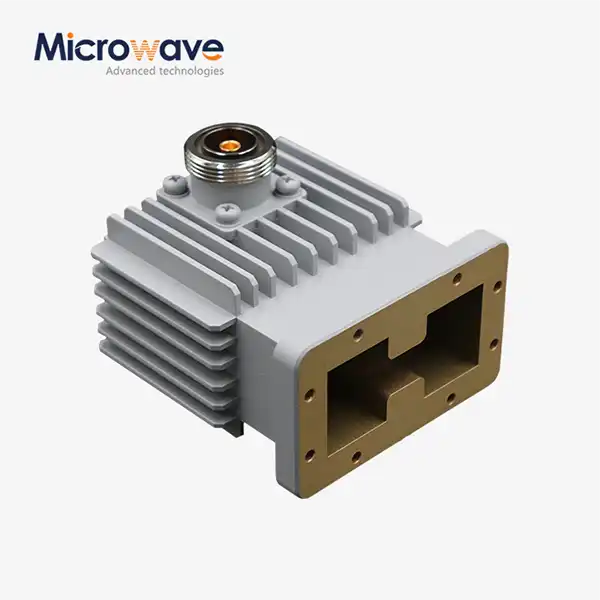 VIEW MOREHigh Power Waveguide to Coaxial Adapter
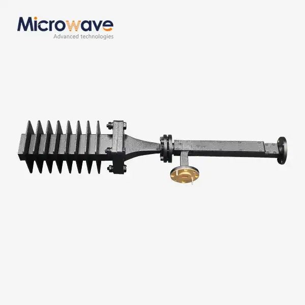 VIEW MOREWaveguide Fixed Attenuator
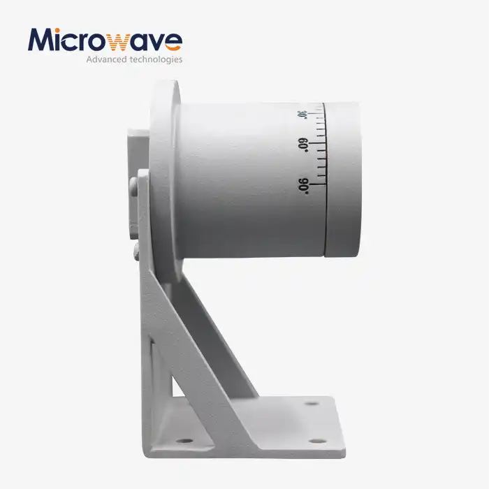 VIEW MORE90° Polarized Rotary Joint
_1733809032116.webp) VIEW MORECoaxial Calibration Kits
VIEW MORECoaxial Calibration Kits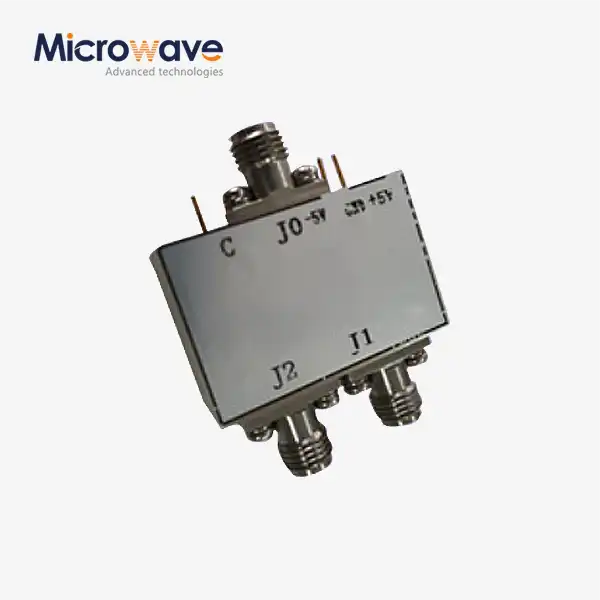 VIEW MOREHigh Power Coaxial Switch
 VIEW MOREMMDS Transmitting Antenna
 VIEW MOREConical Dual circular Polarization Horn Antenna
 VIEW MOREPyramidal Linear Polarization Horn Antenna
