What are the fundamental differences between directional couplers and power dividers in waveguide systems?
Understanding the distinctions between directional couplers and power dividers in waveguide systems is crucial for engineers designing high-frequency communication networks, radar systems, and satellite applications. Both components serve essential roles in signal distribution and measurement, yet they operate on fundamentally different principles and serve distinct purposes. A waveguide coupler, particularly the directional type, provides selective coupling with inherent isolation between ports, while power dividers focus on equal signal distribution without directional sensitivity. This comprehensive analysis explores their operational characteristics, design considerations, and practical applications to help engineers make informed decisions for their specific microwave system requirements.
Operational Principles and Design Fundamentals
Directional Coupling Mechanisms in Waveguide Systems
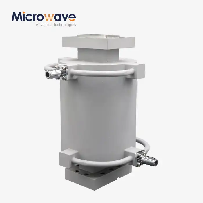
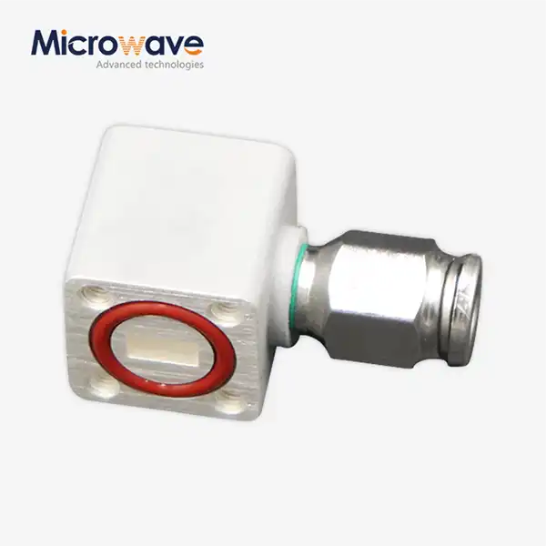
Directional couplers operate on the principle of electromagnetic field coupling between adjacent transmission paths, creating a frequency-dependent transfer of energy that maintains phase relationships and directional sensitivity. The waveguide coupler achieves this through carefully engineered apertures, loops, or probe arrangements that sample a fraction of the forward-traveling wave while providing significant isolation from reflected signals. Advanced Microwave's waveguide loop coupler demonstrates this principle effectively, operating within 20% waveguide bandwidth with a main line VSWR of 1.10 and offering coupling selections from 12 to 60 dB. The directional properties arise from the phase relationships between coupled signals, where forward and reverse waves create constructive interference at the coupled port and destructive interference at the isolated port. This selectivity makes directional couplers invaluable for signal monitoring, power measurement, and system protection applications where distinguishing between forward and reflected power is critical.
Power Division Mechanisms and Equal Distribution
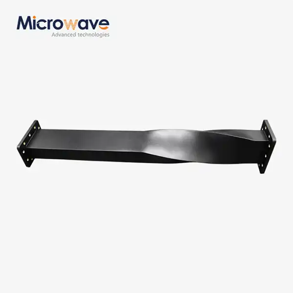
Power dividers function through impedance transformation and signal splitting techniques that prioritize equal amplitude and phase distribution over directional discrimination. Unlike the selective coupling of a waveguide coupler, power dividers employ symmetric junction designs, such as T-junctions, Wilkinson dividers, or hybrid configurations, to achieve predetermined power split ratios while maintaining impedance matching across all ports. The fundamental operation relies on transmission line theory and impedance transformation rather than electromagnetic coupling, resulting in devices that treat forward and reflected signals equally. This bidirectional characteristic means power dividers cannot distinguish between signals traveling in opposite directions, making them unsuitable for applications requiring directional sensitivity. However, their ability to provide precise amplitude and phase relationships makes them essential for antenna arrays, mixer applications, and systems requiring coherent signal distribution.

Isolation and Port Characteristics Comparison
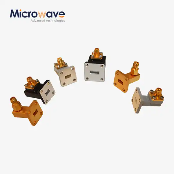
The isolation characteristics between directional couplers and power dividers represent one of the most significant operational differences, directly impacting system performance and application suitability. A waveguide coupler provides excellent isolation between the input and isolated ports, typically exceeding 20 dB and often reaching 40-50 dB in well-designed units like those offered by Advanced Microwave Technologies. This isolation prevents reverse signal coupling, protecting source equipment and enabling accurate power monitoring without loading effects. The four-port configuration of directional couplers (input, output, coupled, and isolated) allows for simultaneous signal transmission and monitoring, with the isolated port often terminated in a matched load to absorb unwanted reflections. Power dividers, conversely, typically offer limited isolation between output ports, focusing instead on impedance matching and equal power distribution. The three-port configuration (input and two outputs) of basic power dividers means reflected signals from one output port can appear at the other output, potentially causing interference in sensitive applications.
Performance Characteristics and Technical Specifications
Frequency Response and Bandwidth Considerations
The frequency response characteristics of directional couplers and power dividers differ significantly due to their underlying operational principles and construction methodologies. Directional couplers, particularly the waveguide coupler designs, exhibit frequency-dependent coupling coefficients that must be carefully characterized across the operating bandwidth. Advanced Microwave's loop couplers demonstrate stable performance across 20% waveguide bandwidth, maintaining consistent coupling values and VSWR characteristics throughout the specified frequency range. The directional properties of these devices are inherently frequency-sensitive, with coupling coefficients typically varying by several decibels across wide bandwidths. This frequency dependence can be advantageous in applications requiring frequency-selective coupling or problematic when broadband operation is essential. Power dividers generally offer more consistent amplitude and phase responses across their operating bandwidth, with designs optimized for minimal insertion loss and excellent port-to-port isolation. The symmetric nature of power divider designs allows for broader bandwidth operation with more predictable performance characteristics.
VSWR Performance and Impedance Matching
Voltage Standing Wave Ratio (VSWR) performance represents a critical specification for both device types, though the implications and measurement approaches differ substantially. The waveguide coupler achieves excellent VSWR performance through careful impedance transformation and coupling mechanism design, with Advanced Microwave's products typically achieving main line VSWR values of 1.10 or better. This low VSWR indicates excellent impedance matching, minimizing signal reflections that could degrade system performance or damage source equipment. The secondary line VSWR of 1.25 in these couplers reflects the impedance characteristics of the coupled port, which must balance coupling efficiency with impedance matching requirements. Power dividers prioritize VSWR performance across all ports simultaneously, requiring more complex impedance transformation networks to achieve matched conditions at multiple ports. The symmetric design of power dividers often results in inherently better VSWR performance at the output ports, though achieving low VSWR at all ports simultaneously can be challenging, particularly in wide bandwidth applications.
Insertion Loss and Coupling Accuracy
Insertion loss characteristics reveal fundamental differences in how these devices handle signal transmission and energy distribution. Directional couplers introduce minimal insertion loss in the main transmission path, typically less than 0.2 dB for well-designed waveguide coupler units, while extracting a predetermined fraction of signal power through the coupled port. The coupling accuracy of directional couplers is critical for measurement applications, with high-quality units maintaining coupling coefficients within ±0.5 dB across their operating bandwidth. Advanced Microwave's precision manufacturing ensures consistent coupling performance, essential for applications requiring accurate power monitoring or signal sampling. The insertion loss in directional couplers remains relatively constant regardless of the coupling coefficient, making them suitable for applications where main line transmission efficiency is paramount. Power dividers exhibit insertion loss characteristics determined by the power split ratio and number of output ports, with theoretical minimum insertion losses of 3 dB for equal-split two-way dividers and 6 dB for four-way divisions, not accounting for resistive losses in the device construction.

Applications and Selection Criteria
Signal Monitoring and Measurement Applications
Signal monitoring applications represent the primary domain where directional couplers excel due to their inherent directional sensitivity and isolation characteristics. The waveguide coupler provides an ideal solution for continuous power monitoring in high-power transmission systems, allowing engineers to sample forward power without disrupting the main signal path or introducing significant insertion loss. Advanced Microwave's loop couplers find extensive application in satellite communication systems, where accurate power monitoring is essential for maintaining optimal signal levels and preventing equipment damage from excessive power levels. The directional properties enable separate monitoring of forward and reflected power, providing critical information about antenna system performance and impedance matching. These applications require the high isolation and coupling accuracy that only directional couplers can provide, making power dividers unsuitable for such demanding measurement requirements. The ability to operate at high power levels while maintaining measurement accuracy makes directional couplers indispensable in radar systems, broadcasting applications, and high-power amplifier testing.
Signal Distribution and Array Feeding Systems
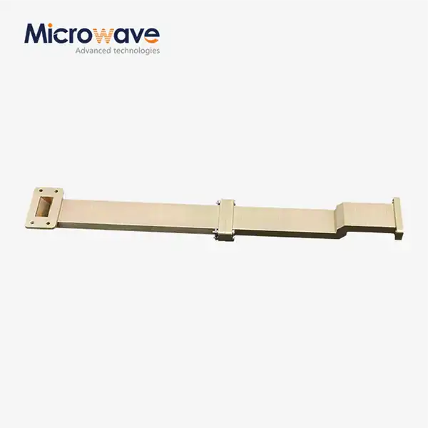
Signal distribution applications favor power dividers due to their symmetric design and equal amplitude/phase characteristics across multiple output ports. Antenna array systems require precise amplitude and phase relationships between array elements to achieve desired radiation patterns and beam steering capabilities. Power dividers excel in these applications by providing equal power division with maintained phase relationships, essential for coherent array operation. While a waveguide coupler could theoretically be used for signal distribution, the unequal power division and directional characteristics make it unsuitable for most array applications where equal element excitation is required. The symmetric design of power dividers ensures that impedance mismatches at one output port minimally affect the other outputs, providing stable operation even with varying load conditions. Advanced Microwave's experience in satellite and aerospace applications demonstrates the critical importance of proper signal distribution in phased array systems, where power dividers enable precise beam control and optimal antenna performance.

System Protection and Isolation Requirements
System protection applications highlight the complementary roles of directional couplers and power dividers in comprehensive microwave system design. The waveguide coupler serves as a protective monitoring device, allowing continuous surveillance of forward and reflected power levels without interrupting system operation. This capability enables automatic shutdown or power reduction when dangerous conditions are detected, protecting expensive transmitter equipment from damage due to antenna system failures or impedance mismatches. The high isolation between input and isolated ports prevents reverse signal coupling that could interfere with sensitive measurement equipment or create instability in active circuits. Power dividers contribute to system protection through their ability to distribute signals to multiple loads, reducing the impact of individual load failures on overall system performance. However, the limited isolation between output ports in power dividers can allow interference between connected systems, requiring careful system design to prevent unwanted interactions. The selection between these devices for protection applications depends on whether directional sensitivity is required and the specific isolation requirements of the application.
Conclusion
The fundamental differences between directional couplers and power dividers in waveguide systems stem from their distinct operational principles and design objectives. Directional couplers provide selective signal sampling with excellent isolation and directional sensitivity, making them ideal for monitoring and measurement applications. Power dividers offer symmetric signal distribution with equal amplitude and phase characteristics, excelling in array feeding and distribution systems. Understanding these differences enables engineers to select the appropriate component for their specific application requirements, optimizing system performance and reliability.
Ready to optimize your waveguide system performance? Advanced Microwave Technologies Co., Ltd. brings over 20 years of manufacturing excellence to deliver precision-engineered solutions for your most demanding applications. Our comprehensive product line includes high-performance waveguide loop couplers, power dividers, and complete antenna systems backed by ISO:9001:2008 certification and RoHS compliance. Whether you need prototyping support for innovative designs or full-scale production for established systems, our expert engineering team provides tailored solutions with quick turnaround times and competitive pricing. From satellite communications to defense applications, our products serve critical roles in aerospace, telecommunications, and radar systems worldwide. Don't let component limitations constrain your project success – contact our technical specialists today to discuss your specific requirements and discover how our advanced manufacturing capabilities can accelerate your development timeline. Reach out to us at mia@admicrowave.com to start your consultation and unlock the full potential of your microwave systems.
References
1. Pozar, D. M. (2012). Microwave Engineering, Fourth Edition. John Wiley & Sons, New York.
2. Collin, R. E. (2001). Foundations for Microwave Engineering, Second Edition. IEEE Press, Piscataway.
3. Matthaei, G. L., Young, L., & Jones, E. M. T. (1980). Microwave Filters, Impedance-Matching Networks, and Coupling Structures. Artech House, Norwood.
4. Montgomery, C. G., Dicke, R. H., & Purcell, E. M. (1987). Principles of Microwave Circuits. Institution of Engineering and Technology, London.
5. Ragan, G. L. (1965). Microwave Transmission Circuits. McGraw-Hill Book Company, New York.
6. Harvey, A. F. (1963). Microwave Engineering. Academic Press, London.