Pyramid Antenna Design Factors for Better RF Performance
When optimizing RF systems for mission-critical applications, pyramid antenna design stands as a cornerstone of reliable signal transmission. These specialized aperture antennas leverage geometric precision and advanced dielectric integration to overcome spherical phase error—a persistent challenge in classical antenna engineering. By incorporating lens elements at the aperture or throat of pyramidal waveguide structures, modern pyramid antennas deliver exceptional directivity in compact form factors, addressing the dual demands of high gain and spatial efficiency that procurement engineers face in defense, satellite, and telecommunications sectors.
Understanding Pyramid Antenna Basics and Design Principles
Pyramid antennas are a complex step forward in the design of RF components. They combine new ideas in geometry with research in materials science to meet the high-performance needs of modern transmission systems. We've seen at Advanced Microwave Technologies Co., Ltd. that knowing these basics helps buying teams make smart choices that match technology requirements with real-world operations.
Core Structure and Operating Mechanism
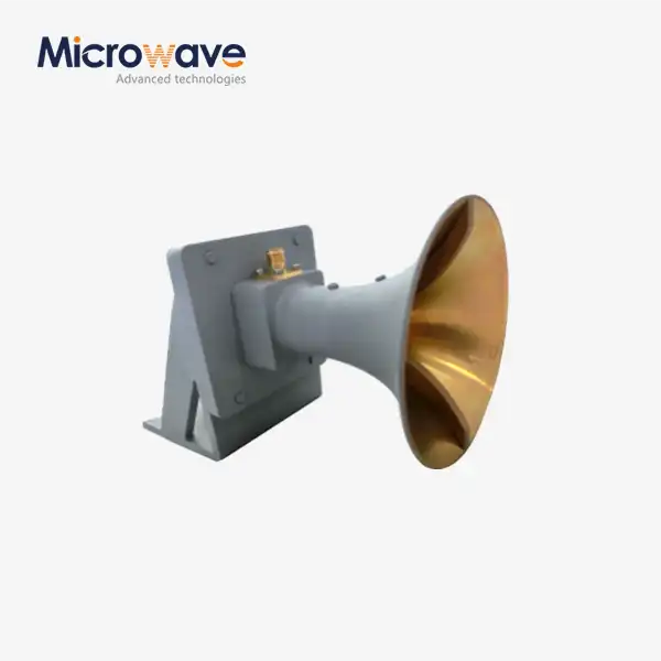
Pyramid antennas combine a pyramidal waveguide flare with a plano-convex or meniscus dielectric lens. This lens phase corrects spherical feed-point wavefronts into flat, uniform aperture wavefronts. Machined from high-conductivity materials like aluminum or copper and coated with silver or gold, the waveguide segment minimizes resistive losses and maintains structural integrity at high temperatures. Dielectric lenses are composed of low-loss materials like PTFE (Teflon), Rexolite, or TPX with precisely regulated loss slope and permittivity. In use, electromagnetic energy passes via the flared waveguide and strikes the lens contact, where refraction balances phase. This correction approach directly addresses path-length disparities in typical horn antennas, where energy flowing to the sides of the aperture travels farther than radiation passing through the center.
Differentiation from Alternative Antenna Technologies
Pyramid antennas utilize lens elements to improve performance at shorter axial lengths, whereas horn antennas merely use flare geometry to modify radiation patterns. Parabolic reflectors concentrate energy well, but they need precise surface tolerances and high mounting support. Patch antennas are tiny but lose gain and bandwidth. Pyramid antennas overcome these issues by combining horn-like directivity with reduced dimensions. In tiny antenna test locations or aerial platforms, where every centimeter restricts cargo capacity, this is a major advantage.
Critical Performance Metrics for Procurement Evaluation
Gain, measured in decibels compared to an isotropic radiator (dBi), indicates how successfully the antenna focuses radiation. Pyramid antennas often achieve 25–35 dBi, matching or exceeding longer ordinary horns. VSWR values below 1.5:1 usually determine the bandwidth, or frequency range, where the antenna functions well. Pyramid designs nowadays may cover the waveguide (X, Ku, Ka) or provide fine frequency control in restricted bands. Efficiency (radiated power to input power) is 90% or more with the correct lens materials and aperture resistance. Side lobe levels (SLL) below -25 dB prevent system interference. Aircraft and defense customers must carefully analyze this characteristic. Engineering teams utilize these parameters to determine whether a configuration is suitable for radar calibration, satellite ground terminals, or OTA testing.
Key Design Factors Influencing RF Performance
Designers must consider how design parameters impact pyramid antenna systems' electromagnetic performance, mechanical durability, and lifetime cost to improve them. After 20 years in production, we've observed how modest changes to specifications may affect military and telecommunications operations.
Aperture Geometry and Dimensional Optimization
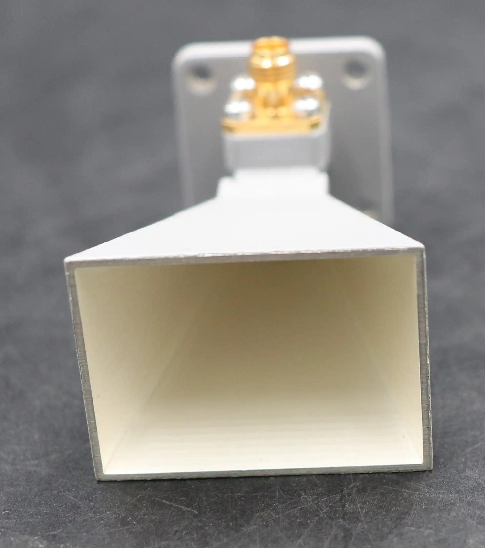
Aperture size is the major gain-beamwidth trade-off. Larger apertures concentrate energy into smaller beams, increasing gain and limiting the viewing angle. This makes them ideal for precisely aligned point-to-point satellite lines. Smaller apertures improve beamwidth, making ground-based radar sweeping simpler. The aperture aspect ratio (width to height) impacts polarization purity and cross-polarization discrimination, which reduce interference in regions with plenty of spectral information. Rectangular apertures support linear polarization, whereas square apertures may accommodate dual-polarized lines for horizontal and vertical transmissions. Weight matters in airplanes because every gram affects fuel usage and capacity. Our engineers must balance electromagnetic and mechanical concerns. They employ honeycomb core structures or composite materials to reduce weight without compromising stiffness.
Material Selection for Conductivity and Environmental Resilience
Conductor material affects performance and durability. Copper is an excellent conductor, but improper plating oxidizes it, reducing its conductivity. Silver plating offers the highest conductivity and corrosion resistance; however, gold plating may be cheaper for intermediate performance and extended service life applications. Aluminum is less conductive but has a greater strength-to-weight ratio, making it preferable for mobile and flying devices. The choice of dielectric lens material is crucial. PTFE has negligible dielectric loss (tan δ < 0.001) at microwave frequencies and maintains its characteristics from -55°C to +125°C. Outdoor satellite stations vulnerable to weather need this. TPX (polymethylpentene) reduces weight further, but high-power usage needs heat regulation. Material homogeneity maintains the lens volume dielectric constant. However, localized phase errors from impurities or voids boost side lobes and diminish gain. ADM selects materials from recognized vendors and uses laser profilometry to maintain lens surface tolerances within λ/50. We ensure the phase adjustment mechanism works properly.
Frequency Range Engineering and Bandwidth Considerations
Single-band pyramid antennas optimize all parameters for a narrow frequency range. This makes them ideal for 77–81 GHz automobile radar, where operating bands are restricted. Broadband designs for multiple services or tunable systems need careful impedance matching over octaves or multi-octaves. Lens thickness and curvature affect frequency response. Thick lenses improve phase correction but increase frequency-dependent transmission coefficients. Waveguide feed-to-throat transitions must maintain low VSWR over the desired frequency. They employ stepped or ridged designs to handle impedance change. Our laboratories use vector network analyzers up to 110 GHz to assess S-parameters throughout all operating ranges for resonances or mismatches that might affect field performance. This verification ensures that the items fulfill the buy standards for insertion loss and return loss.
Polarization Management and Radiation Pattern Control
System capacity and interference avoidance depend on polarization purity. Linear polarization works effectively for land-based point-to-point communications with constant antenna orientation. In satellite communications, circular polarization minimizes multipath fading and Faraday rotation. To create orthogonal E-field components of identical size and 90-degree phase offset, specific feed designs are needed. Cross-polarization discrimination (XPD) detects undesired orthogonal polarization and is frequently over 30 dB. Poor XPD leaks signals onto adjacent channels, reducing spectrum efficiency. The lens profile and aperture tapering affect the radiation pattern, main beam width, and side lobe spread. Research institutes require low side lobes to avoid ground congestion for atmospheric observations. Defense surveillance systems discover threats across vast angles by balancing main beam gain with side lobe coverage. We customize patterns using aperture field synthesis and forecast performance before manufacture using computational electromagnetics. This reduces development time and risk for OEM partners using our antennas in larger systems.
Comparative Analysis: Pyramid Antenna vs. Other Antenna Types
To choose the best pyramid antenna design, you have to weigh performance metrics against the needs of the application and your budget. This comparison approach helps procurement managers make sure that technology needs are met while also taking into account how the system will be deployed.
Performance and Form Factor Trade-offs
Traditional pyramidal horn antennas without lens elements offer a gain of 15–25 dBi but need longer axial lengths to reduce phase inaccuracy. An X-band horn with 20 dBi gain may be 30 cm long, making it difficult to incorporate into tiny systems. Pyramid horn lens antennas may be fitted in equipment racks or conformal aircraft installations since they have the same gain in half the length. Parabolic reflector antennas provide 30–50 dBi gain for satellite ground terminals but necessitate wind-resistant mounting structures. Their enormous apertures need precise alignment devices, making installation and maintenance harder. WiFi and cellular base stations use low-profile patch antenna arrays. However, single-element gains seldom exceed 8 dBi, requiring array arrangements with feed network losses. Center pyramid antenna. It has more gain than patches, is smaller than parabolic dishes, and is simpler to produce than phased arrays.
Application-Specific Suitability Assessment
Satellite ground stations utilize pyramid antennas to feed systems that light up larger mirrors because their regulated radiation patterns reduce Earth-based interference and transfer losses. The lens-corrected image accelerates energy to the reflector surface, increasing system gain. Compact antenna test ranges (CATR) imitate far-field situations in tiny lab areas using the antenna's capacity to deliver plane waves across short distances for defense radar calibration. Our 24-meter microwave darkroom characterizes 110-GHz systems using this concept. Pyramid antennas are end-of-line testing requirements for automobile radar manufacturing lines. Their consistent beam patterns and strong directivity allow repeated measurements, which are crucial for quality control. These antennas are used in 5G millimeter-wave base stations and backhaul lines because their gain, bandwidth, and tiny size make them cost-effective and simple to install.
Selection Criteria for B2B Procurement Decisions
Frequency band compatibility dominates the option matrix. Make sure that the antenna's operational range covers all channels, allowing for component tolerances and environmental fluctuations. Temperature, humidity, vibration, and shock must meet deployment parameters. MIL-STD-810 requires sealed designs with UV-resistant radomes and rust-resistant hardware for outdoor use. The initial cost should be compared to the ongoing expenditures. Higher-quality materials and tighter tolerances cost more upfront but last longer and need less maintenance, lowering the total cost of ownership. Installation challenges project timeframes. Plug-and-play antennas with mounting hardware are easier to install than those that need alignment tools and professional technicians. When typical catalog items don't fulfill demands, customisation is crucial. OEM services, quick prototyping, and engineering cooperation can provide the optimum performance-to-cost solutions.
Installation, Maintenance, and Technical Considerations
Realizing the full performance potential of a pyramid antenna requires careful placement and ongoing operating management. These factors have a direct effect on data clarity, system uptime, and return on capital investment.
Installation Techniques and Alignment Procedures
The appropriate mounting ensures stability under environmental pressures and electromagnetic alignment. Fastener torque specifications prevent waveguide flange deformation, which lowers VSWR and causes loss. Different applications need different alignments. Satellite stations are positioned within 0.1 degrees of azimuth and elevation using measuring equipment or GPS-based pointing devices. Before turning on the system, fiber-optic borescopes and laser alignment instruments verify mechanical midline correctness. When changing cables, avoid steep bends, which increase insertion loss and electromagnetic interference. For high outdoor installations, grounding connections prevent static electricity and safeguard against lightning. Our technical support staff provides product-specific installation instructions. Torque values, connection interface standards, and test methods are provided to ensure appropriate installation.
Diagnostic Approaches and Preventive Maintenance Strategies
Signal loss is often caused by connection corrosion, water intrusion, or mechanical stress fractures. Portable network testers do frequent VSWR sweeps to detect impedance issues before transmission issues arise. Visual inspections reveal fractured radomes and deteriorated attachment gear. Periodically cleaning lens surfaces with permitted solutions is required because abrasive materials or chemicals that don't interact well with PTFE might scratch or modify its characteristics, affecting phase correction. Replacement of desiccant packs in sealed containers is advised by the manufacturer. This prevents dielectric loss-raising condensation. Preventive maintenance programs balance operational availability with maintenance frequency. Telecom firms may need off-peak inspections every three months, whereas defensive systems are completely examined during planned maintenance intervals. Predictive maintenance may replace parts before they break down and discontinue operations by recording performance data.
Upgrade Pathways and Customization Options for Evolving Requirements
System improvements without replacement are typically needed as technology and missions evolve. Expanding frequency bands using lens designs or waveguide transitions accommodates new spectral allocations. 5G might add millimeter-wave bands to infrastructure. Linear to circular polarization adjustments assist with satellite constellations or services. For hard-to-see bases, radar dome changes make them more climate-resistant or decrease the radar cross-section. Large-scale purchases might benefit from manufacturers offering bulk savings, specialist engineering skills, and supply chain priority during component shortages. ADM's flexible manufacturing allows us to handle batch orders with particular criteria. Our integrated supply chain and ISO 9001:2015-certified quality standards provide consistent outcomes for hundreds of pieces and enable quick prototyping for unique forms or material combinations.
Procurement Insights: How to Choose and Buy Pyramid Antennas for Your Business
Strategic buying of pyramid antennas depends on evaluating suppliers, making sure they meet technical requirements, and coordinating the supply chain. These are the things that make the difference between successful deployments and costly mistakes.
Supplier Assessment and Quality Verification
Reliable manufacturers have been in business for a long time, have ISO 9001 for quality management, ISO 14001 for environmental stewardship, and ISO 45001 for occupational health and safety, and have proof that they follow government rules like RoHS for hazardous substance limits. VSWR graphs throughout operating bands, far-field radiation patterns obtained in calibrated anechoic chambers, and environmental stress screening findings are key metrics. Third-party lab reports might be used to verify internal testing results. Visit a manufacturing site to learn how they create goods, how they verify quality, and how much they spend on measurement equipment. Strict validation up to 110 GHz requires capital investments like our 24-meter microwave darkroom with antenna plane near- and far-field measurement recombination chamber. Quickly answering technical questions before a sale indicates strong after-sales service. Providers providing application notes, simulation data, and technical presentations demonstrate customer care.
Pricing Analysis and Total Cost of Ownership
Custom parts require more time, money, and resources to develop and build; therefore, catalog prices are for basic configurations. Buying a specified quantity of copies allows for tiered pricing. If you commit to 100 units, the cost per unit may be reduced by 20–30% compared to ten units, and if you commit to 1,000 units, you may employ dedicated manufacturing lines for even greater economies of scale. Check the manufacturer and performance warranties. Longer warranties (three to five years) demonstrate the manufacturer's confidence and reduce replacement costs. Delivery time and cost depend on shipping methods. You must pay customs duties, freight insurance, and import procedures when purchasing abroad. Getting things from inside the nation simplifies logistics, yet it may cost more or eliminate talent. Lifecycle expenses include calibration, part availability, and obsolescence. Choose vendors with lengthy product lifecycles and backward compatibility to prevent upgrading as parts wear out.
Emerging Technologies and Future-Proofing Strategies
While 6G research focuses on D-band (110–170 GHz) for ultra-high-capacity wireless connections, millimeter-wave and sub-THz applications push pyramid antenna advancement. Advanced metamaterial lenses enable dynamic beam steering without mechanical motion mechanisms. This lets multi-mission platforms with electrically reconfigurable apertures. Unlike conventional machining, additive manufacturing (3D printing) can create complicated forms. This might reduce lead times and speed design modifications. ISAC systems utilize the same apertures for radar and data transmission; hence, they require antennas designed for both. Companies should consider their suppliers' innovation objectives, R&D spending, and standard-setting efforts when making procurement decisions. Businesses may test new technologies before mass production by cooperating with prototype makers. This reduces technical risk and positions firms to benefit from technology improvements.
Conclusion
Using pyramid antennas to get better RF performance means combining electromagnetic theory with real-world engineering limitations. The operational requirements of a system are based on its aperture geometry, material properties, frequency characteristics, and polarization management. By comparing one type of antenna to others, application-specific benefits become clear, which helps buying teams find the most cost-effective options. Precision in installation and preventative maintenance keeps things running smoothly for the whole service life. Strategic ties with suppliers allow for adaptation and the use of new technologies in the future. Companies that spend a lot of time and money on lifecycle planning, thorough technical validation, and careful source review will get the most out of pyramid antenna operations in the defense, aerospace, satellite, and telecommunications sectors. Since the 2000s, we've been making precise RF components that show how paying attention to these design factors leads to systems that are reliable, perform well, and go beyond what the mission calls for.
Frequently Asked Questions
Why select a pyramid horn lens antenna instead of a conventional horn design?
The built-in lens fixes the spherical phase error, which makes it possible for much higher gain and lower side lobe levels in a smaller package. Standard horns with the same performance need a much longer axial length, which makes them harder to use in places with limited space, like small test ranges or installations in the air, where every centimeter affects the overall system design.
What frequency ranges suit pyramid antenna applications best?
Microwave and millimeter-wave bands, usually from 18 GHz to 110 GHz, are where these antennas work best. They can handle K-band satellite communications, car radar at 77–81 GHz, and new 6G studies in W-band and D-band. When frequencies are low, different forms are often preferred because size restrictions don't matter as much.
How does lens material affect power handling capacity?
Waveguide sections filled with air have higher breakdown limits than waveguide sections made of dielectric materials. Although it works well for most measuring and receiving tasks, high-power transmission needs to be analyzed thermally to keep the lens from overheating or the voltage from dropping. This could mean that forced cooling or power de-rating techniques are needed.
Can pyramid antennas support near-field measurement applications?
Of course. Because the aperture creates a flat wavefront, these antennas are great tools for near-field scanning devices that need precise control over phase and amplitude distribution. In antenna diagnostics and electromagnetic compatibility tests, where field consistency directly affects measurement accuracy, this trait is very important.
Partner with ADM for Your Pyramid Antenna Requirements
Advanced Microwave Technologies Co., Ltd has been a specialist in pyramid antennas for more than 20 years and helps customers all over the world find trusted providers. Our modern measurement facilities up to 110 GHz, ISO-certified quality systems, and ability to design and manufacture all at the same time make sure that every part meets the strict requirements for satellite communications, defense radar, and internet infrastructure. Our engineering team works closely with procurement professionals to improve performance, keep costs low, and speed up delivery times, no matter if you need standard catalog products or custom OEM solutions. You can email our technical experts at craig@admicrowave.com with your specific needs, and we'll look into how our waveguide assemblies, precision antennas, and full support services can help you solve your most important RF problems. Defense companies, satellite operators, and research institutions trust us for high-reliability uses because we can make quick prototypes, have a global logistics network, and offer quick customer service after the sale.
References
1. Balanis, Constantine A. Antenna Theory: Analysis and Design. 4th ed. Hoboken: John Wiley & Sons, 2016.
2. IEEE Standard 149-2021. IEEE Standard for Test Procedures for Antennas. New York: Institute of Electrical and Electronics Engineers, 2021.
3. Milligan, Thomas A. Modern Antenna Design. 2nd ed. Hoboken: John Wiley & Sons, 2005.
4. Olver, A. D., et al. Microwave Horns and Feeds. London: IET Electromagnetic Waves Series, 1994.
5. Pozar, David M. Microwave Engineering. 4th ed. Hoboken: John Wiley & Sons, 2011.
6. Silver, Samuel. Microwave Antenna Theory and Design. New York: McGraw-Hill Book Company, 1949.