


BLOG
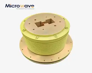
Double Ridge Waveguide Rotary Joint: What It Is and How It Works
March 23, 2026
When engineers need to transfer microwave signals from stationary equipment to rotating components, traditional waveguides fall short. Double Ridge Waveguide Rotary Joint: What It Is and How It Works represents a breakthrough solution that enables continuous signal transmission during mechanical rotation. These specialized electromechanical devices serve critical roles in radar systems, satellite communications, and aerospace applications where reliable microwave energy transfer between fixed and rotating assemblies remains paramount.
Top Plastic Flange Caps Uses in Pipeline and Valve Systems
March 23, 2026
Plastic Flange Caps serve as essential protective components in modern pipeline and valve systems, safeguarding critical infrastructure across industries worldwide. These specialized covers protect flanged connections from contamination, corrosion, and mechanical damage during transportation, storage, and maintenance operations. The growing demand for reliable sealing solutions has driven innovation in flange protection technology, particularly in high-precision applications where signal integrity remains paramount. Industries ranging from petrochemicals to telecommunications rely on these protective devices to maintain system performance and extend equipment lifespan. Advanced manufacturing techniques now enable production of caps that withstand extreme environmental conditions while providing cost-effective protection. Understanding the diverse applications of plastic flange protectors helps procurement professionals make informed decisions for their specific operational requirements.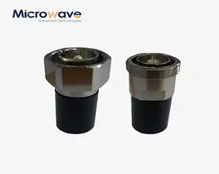
Coaxial Load Applications in Telecom and Test Systems
March 23, 2026
Coaxial Load applications in telecom and test systems serve as critical termination components that absorb radio frequency energy while maintaining precise impedance matching. These passive devices prevent signal reflections, protect sensitive equipment from damage, and ensure optimal system performance across various telecommunications infrastructure, laboratory testing environments, and measurement applications. By converting unwanted RF energy into heat, coaxial loads enable engineers to maintain signal integrity and achieve accurate calibration results.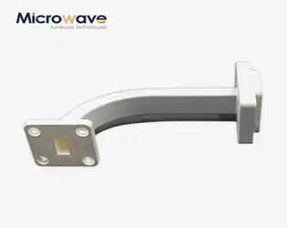
Waveguide E Bend Applications in Aerospace & Defense Systems
March 20, 2026
Waveguide E bend technology serves as a cornerstone component in modern aerospace and defense systems, enabling precise electromagnetic signal routing through complex network architectures. These specialized microwave components facilitate controlled directional changes in signal propagation while maintaining exceptional signal integrity across demanding operational environments. Advanced Microwave Technologies Co., Ltd. provides comprehensive Waveguide E Bend solutions spanning WR10 through WR430 sizes, supporting frequencies up to 110 GHz with customizable configurations for mission-critical applications. Our precision-engineered components deliver reliable performance in satellite communications, radar systems, and electronic warfare platforms where signal degradation is not acceptable.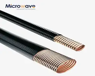
Why Choose Elliptical WG for High-Frequency Communication
March 20, 2026
Elliptical WG represent a revolutionary solution for high-frequency communication challenges, offering superior signal transmission capabilities compared to traditional rectangular waveguides. The elliptical geometry provides exceptional electromagnetic field confinement while maintaining flexible installation characteristics essential for modern communication infrastructure. These specialized transmission lines combine the low-loss properties of rigid waveguides with the adaptability of flexible systems, making them indispensable for satellite communications, radar systems, and defense applications where signal integrity cannot be compromised.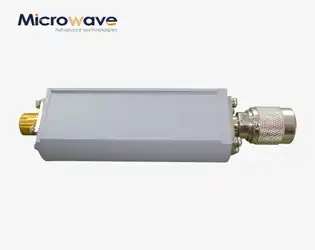
Best Coaxial Detector Models for Broadband Signal Monitoring
March 20, 2026
The best coaxial detector models for broadband signal monitoring combine high detection sensitivity, minimal standing wave coefficients, and exceptional overload capacity to deliver precise signal measurement across wide frequency ranges. These advanced RF components feature specialized point contact diodes and optimized broadband matching circuits that ensure reliable performance in mission-critical applications including defense radar systems, satellite communications, and electronic warfare environments where signal integrity directly impacts operational success.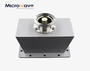
OEM End Launch Waveguide to Coaxial Adapter Supplier Guide
March 18, 2026
Finding the right OEM End Launch Waveguide to Coaxial Adapter supplier requires understanding technical specifications, customization capabilities, and manufacturing excellence. These critical RF components bridge waveguide and coaxial transmission systems, making supplier selection vital for your project success. Advanced Microwave Technologies (ADM) delivers comprehensive OEM solutions with over two decades of microwave engineering expertise, ISO certifications, and full customization capabilities spanning frequencies up to 110 GHz for aerospace, defense, telecommunications, and satellite communication applications.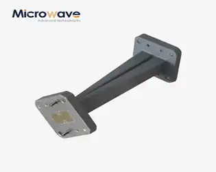
Best Double Ridge Twist Waveguide Designs for 5G & Radar
March 18, 2026
When searching for optimal Double Ridge Twist Waveguide solutions for next-generation 5G networks and advanced radar systems, engineers prioritize broadband performance, compact design, and exceptional signal integrity. The best designs combine precision manufacturing with innovative ridge geometry to achieve multi-octave bandwidth capabilities while maintaining low VSWR and minimal insertion loss. These specialized microwave components address critical space constraints in modern communication infrastructure while delivering the reliability demanded by mission-critical applications in defense, aerospace, and telecommunications sectors.
