


BLOG
Miter Bend Waveguide: Design, Applications, and Key Benefits Explained
April 13, 2026
When engineers are limited on space in high-frequency radio frequency (RF) systems, they often find that a precisely engineered part that bends electromagnetic waves at sharp angles without affecting the signal integrity is the best way to solve the problem. This is done by a Miter Bend Waveguide having a reflective plane at the corner, usually a Miter Bend Waveguide at a 45-degree angle. This gets rid of the bulk of normal curved bends while still having low insertion loss and great return loss performance. This new shape is now needed everywhere, especially in defense, telecommunications, and aerospace, where every millimeter counts, and dependability can't be compromised.
How WG Probe Coupler Improves Signal Stability
April 10, 2026
WG Probe Coupler technology changes the way signals are stabilized by making the electromagnetic transition between coaxial transmission lines and rectangular waveguides very exact. These specialised parts make sure that the signal integrity stays the same in all important microwave uses by matching impedances more accurately and reducing reflection losses. A quarter-wave monopole design changes TEM mode signals to TE10 mode transmission, which gets rid of common signal degradation problems that happen in high-frequency systems. WG Probe Coupler solutions provide the stable signals needed for mission-critical radar, satellite communication, and precise measurement tasks in the aerospace and defence industries by keeping high VSWR performance and lowering changes in insertion loss.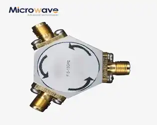
Broadband Coaxial Circulator: Working Principle and RF Applications Guide
April 10, 2026
Engineers often find that a precisely engineered Broadband Coaxial Circulator part that bends electromagnetic waves at sharp angles without affecting the integrity of the signal is the best way to deal with limited space in high-frequency radio frequency (RF) systems. A Broadband Coaxial Circulator does this by having a reflective plane at the corner, usually at a 45-degree angle. This gets rid of the bulk of typical curved bends while keeping low insertion loss and high return loss. This new geometry is now needed everywhere, especially in defense, telecommunications, and aerospace, where every millimeter counts, and dependability can't be compromised.
Broadband Coaxial Circulator: Key Benefits for High-Frequency Transmission
April 10, 2026
When sourcing RF components for mission-critical systems, technical buyers consistently face a fundamental challenge: how to route high-frequency signals unidirectionally while protecting sensitive amplifiers from destructive reflected power. Broadband coaxial circulators solve this pain point by enabling non-reciprocal signal flow across expansive Broadband Coaxial Circulator frequency ranges—typically DC to 40 GHz—without requiring hardware changes during frequency hopping operations. Unlike narrowband alternatives, these three-port devices maintain consistent insertion loss and isolation performance across multiple octaves, reducing system complexity and eliminating the need for switchable component banks in electronic warfare, satellite communications, and wideband radar applications.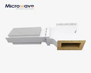
Working principle of the isolator in microwave
April 9, 2026
It is because microwave isolators are non-reciprocal Industrial Microwave Isolator ferrite devices that only let electromagnetic energy flow in one way that they work. An Industrial Microwave Isolator works by using magnetised ferrite materials to make asymmetric propagation features. This stops signals from being reflected while keeping forward transmission going. This very important part keeps delicate microwave gear safe from standing waves and impedance mismatches that could damage pricey source parts like magnetrons and amplifiers in high-power industrial settings.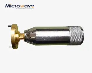
Industrial Microwave Sliding Short in Waveguide Systems: Key Benefits
April 9, 2026
Managing impedance is very important Industrial Microwave Sliding Short when working with high-frequency RF and microwave systems because it can make or break how well the system works. By moving a movable short circuit around inside a waveguide structure, a waveguide sliding short is a precision-engineered part that can change the reflection coefficient. Engineers can fine-tune standing wave patterns, improve power transfer, and keep sensitive source equipment safe from too much reflected energy with this tuning device. Advanced Microwave specializes in high-performance waveguide sliding shorts, which are core tuning parts made for finely adjusting the reflection coefficient in RF and microwave systems. Our sliding shorts are made to meet the tough needs of industrial heating, test and measurement, and communication systems. They have high positioning accuracy, stable reflection performance, and broadband compatibility.
How Broadband Coaxial Circulator Improves Signal Isolation in RF Systems
April 9, 2026
One of the hardest things about designing high-frequency Broadband Coaxial Circulator microwave systems is making sure that electromagnetic signals can go around corners without losing any of their strength. As a well-thought-out solution, the Broadband Coaxial Circulator stands out. It uses a unique 45-degree reflective plane at sharp corners to efficiently redirect microwave energy. These small parts are better for places where space is limited, like in defense radar, satellite payloads, and telecommunications infrastructure, where every cubic centimeter counts. Our in-depth guide breaks down the structural engineering, material science, and industrial use of these important RF components. It gives procurement engineers and technical decision-makers useful information for finding and integrating these parts.
WG Probe Coupler: Structure and Function Explained
April 8, 2026
A WG Probe Coupler is a precision-engineered Radio Frequency (RF) inactive part that acts as the important link between coaxial transmission lines and square or round waveguides. This unique electromagnetic transition device has a metallic probe inside—basically a quarter-wave monopole antenna—that sticks out into the waveguide cavity to trigger or pull out certain electromagnetic modes, most often the dominant TE10 mode. Professional RF engineers use WG Probe Couplers to fix basic impedance mismatches between 50-ohm coaxial systems and waveguide characteristic impedances. This makes sure that signals are transferred smoothly and reflection losses are kept to a minimum in high-frequency applications spanning from Ka-band to millimetre-wave systems.
