Coplanar Waveguide: Advantages and Disadvantages
In the high-frequency RF and microwave circuit design landscape, engineers face a persistent challenge: balancing signal integrity with manufacturing complexity while meeting stringent performance requirements. Traditional transmission line structures often fall short when dealing with millimeter-wave frequencies, tight space constraints, or demanding integration needs. This is where coplanar waveguide (cpw waveguide) technology emerges as a transformative solution. Understanding the advantages and disadvantages of CPW waveguides enables designers to make informed decisions for applications spanning 5G communications, satellite systems, radar technology, and beyond. This comprehensive guide explores how cpw waveguide structures deliver exceptional performance while addressing the critical tradeoffs engineers must navigate in modern high-frequency circuit design.
Understanding CPW Waveguide Fundamentals
The cpw waveguide represents a distinctive planar transmission line architecture characterized by its unique geometrical configuration. Unlike conventional microstrip lines where the signal conductor sits above a ground plane on the opposite side of the substrate, a cpw waveguide features a central conductive strip flanked by two parallel ground planes—all positioned on the same surface of a dielectric substrate. This coplanar arrangement fundamentally changes how electromagnetic energy propagates through the structure. The electromagnetic fields in a cpw waveguide exist partially within the dielectric substrate and partially in the air above it, creating what engineers call an inhomogeneous medium. This characteristic prevents true transverse electromagnetic mode propagation, instead supporting quasi-TEM modes at lower frequencies and transitioning to transverse electric modes at higher frequencies. The field distribution concentrates primarily between the center conductor and the adjacent ground planes, with field lines following paths through both the substrate material and the surrounding air. This unique field pattern directly influences the waveguide's impedance characteristics, loss behavior, and electromagnetic confinement properties. For optimal performance, substrate height should typically be at least twice the slot width to minimize electromagnetic energy leakage into free space, ensuring that signal energy remains tightly coupled to the intended propagation path.
Key Design Parameters of CPW Waveguide Structures
The characteristic impedance of a cpw waveguide depends critically on the lateral dimensions—specifically the width of the center conductor and the spacing between the conductor and ground planes. Unlike microstrip transmission lines where substrate thickness significantly affects impedance, cpw waveguide impedance remains largely independent of substrate thickness, provided the substrate is sufficiently thick relative to the lateral dimensions. This property offers designers substantial flexibility in material selection and manufacturing processes. Engineers can achieve a wide impedance range with cpw waveguide designs, typically spanning from approximately twenty ohms to over two hundred ohms. Lower impedance values require maximizing the center strip width while minimizing the slot spacing, whereas higher impedances necessitate narrow conductors with wider gaps. Advanced Microwave Technologies Co., Ltd.'s CPW waveguide products are designed to minimize signal transmission loss through precise control of these dimensional parameters. The company's expertise in high-frequency transmission line design ensures optimal impedance matching across demanding applications, with products capable of operating from DC to twenty gigahertz with voltage standing wave ratios maintained below specified thresholds throughout the operating band.
Major Advantages of CPW Waveguide Technology
Superior Integration and Manufacturing Benefits
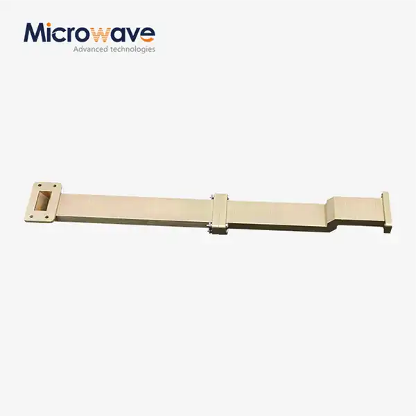
One of the most compelling advantages of cpw waveguide technology lies in its planar structure, which dramatically simplifies both fabrication and integration with other circuit components. Since all metallization resides on a single surface, cpw waveguide circuits can be manufactured using standard planar printed circuit board or monolithic microwave integrated circuit processes. This compatibility with established manufacturing techniques translates directly into cost advantages and production scalability. The single-layer metallization approach eliminates the need for through-substrate vias in many scenarios, reducing manufacturing complexity and potential failure points. Advanced Microwave Technologies Co., Ltd. offers high-performance CPW waveguides with this planar structure, enabling easy integration with other planar components for compact designs. When designers need to incorporate passive components such as capacitors, inductors, or resistors, these elements can be mounted directly adjacent to the cpw waveguide with minimal parasitic effects. The precisely defined ground planes flanking the center conductor provide excellent electromagnetic isolation, reducing unwanted coupling between adjacent signal paths even in dense circuit layouts. This isolation characteristic proves especially valuable in modern communication systems where multiple high-frequency signals must coexist in confined spaces without mutual interference.
Exceptional High-Frequency Performance
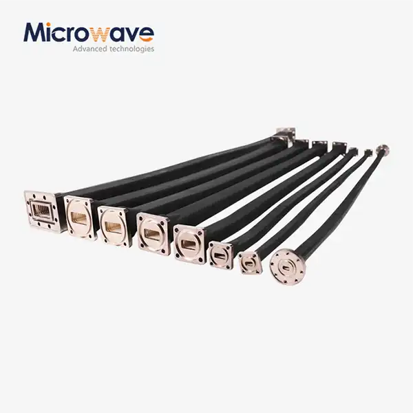
The cpw waveguide structure delivers outstanding electrical performance across broad frequency ranges, particularly excelling in millimeter-wave applications. These waveguides shine in electrical performance, minimizing losses and enabling precise impedance control for excellent circuit matching. The coplanar geometry confines electromagnetic fields primarily within the substrate and the immediate air gap, significantly reducing radiation losses compared to open transmission line structures like conventional microstrip. Advanced Microwave Technologies Co., Ltd.'s cpw waveguide products feature low signal loss characteristics achieved through high-quality materials and optimized geometrical configurations. The company's designs reduce both resistive losses in the conductors and dielectric losses in the substrate material, ensuring efficient high-frequency signal transmission with minimal attenuation. With test frequency ranges spanning from half a gigahertz to one hundred ten gigahertz in their advanced measurement facilities, the company validates performance across the spectrum from traditional wireless bands through cutting-edge millimeter-wave frequencies supporting emerging five-G and anticipated six-G technologies. The wideband performance of cpw waveguide structures stems from their support of single-mode operation across extensive frequency ranges. Unlike some transmission line configurations that experience problematic mode transitions or dispersion effects, properly designed cpw waveguides maintain consistent propagation characteristics throughout their operating bandwidth. This broadband capability makes cpw waveguide technology particularly attractive for applications requiring simultaneous operation across multiple frequency bands or ultra-wideband signal processing.
Design Flexibility and Impedance Control
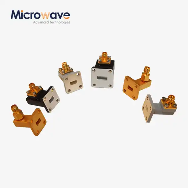
Advanced Microwave Technologies Co., Ltd.'s cpw waveguide offerings provide great design flexibility, customizable for various applications like five-G communications, radar systems, and satellite platforms. By adjusting the conductor width and spacing between the center strip and ground planes, engineers can accurately tune the characteristic impedance for seamless matching with connected components. This precise impedance control reduces signal reflections at interfaces, boosting overall system performance and maintaining signal integrity throughout the transmission path. The ability to realize a wide range of impedance values within a planar structure enables creative solutions to challenging design problems. For instance, designers can implement impedance transformers or matching networks directly within the cpw waveguide medium without requiring additional discrete components. The lateral geometry also facilitates the creation of discontinuities, bends, and transitions that would be difficult or impossible to achieve with other transmission line types. This geometric flexibility extends to the implementation of passive circuit elements such as couplers, filters, and resonators, all realized within the cpw waveguide format while maintaining excellent electromagnetic performance.
Critical Disadvantages and Design Challenges
Increased Losses Compared to Enclosed Structures
While cpw waveguide technology offers numerous advantages, it also presents certain limitations that designers must carefully consider. One significant disadvantage involves higher losses compared to fully enclosed transmission line structures like stripline. The exposed nature of the cpw waveguide means that electromagnetic energy can couple to surface waves propagating along the substrate-air interface, resulting in power loss mechanisms not present in shielded configurations. These surface wave losses become increasingly problematic at higher frequencies and on thicker substrates with higher dielectric constants. The partial exposure of fields to the surrounding environment also creates opportunities for unwanted radiation, particularly at discontinuities, bends, or impedance transitions in the cpw waveguide path. Although Advanced Microwave Technologies Co., Ltd. addresses these challenges through careful material selection and optimized geometrical designs, achieving the lowest possible insertion loss requires meticulous attention to fabrication tolerances and substrate properties. The company's products maintain insertion loss specifications below specified maximum values, but designers must still account for these inherent loss mechanisms when budgeting system link margins or planning power amplifier requirements.
Sensitivity to Adjacent Structures and Fabrication Tolerances
Another significant challenge with cpw waveguide technology involves its sensitivity to nearby circuits and structures. The partially exposed electromagnetic fields make cpw waveguide performance susceptible to influence from components or metallization placed in proximity to the transmission line. This sensitivity complicates efforts to miniaturize circuit dimensions or pack multiple functions into constrained areas, as adequate spacing must be maintained to prevent degradation of the cpw waveguide's electrical characteristics. Fabrication tolerances also critically impact cpw waveguide performance more severely than some alternative transmission line structures. Small variations in the center conductor width or the gap spacing directly alter the characteristic impedance, potentially causing impedance mismatches and degraded return loss. Advanced Microwave Technologies Co., Ltd. leverages state-of-the-art manufacturing technology to ensure high-precision production, maintaining tight dimensional control that minimizes performance variations across production quantities. However, designers must still carefully consider tolerance stackups and specify appropriate manufacturing capabilities when selecting vendors for cpw waveguide circuit fabrication.
Thermal Management Considerations
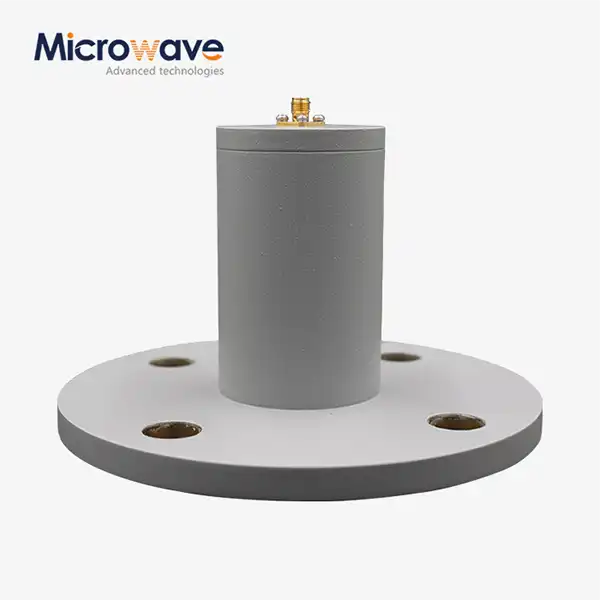
Although cpw waveguide structures provide good heat dissipation through adjacent ground planes that help remove thermal energy from the center conductor, thermal management remains a consideration in high-power applications. The planar geometry concentrates heat generation in a relatively small cross-sectional area, and the partially air-coupled nature of the structure limits the available thermal conduction paths compared to fully substrate-embedded transmission lines. Advanced Microwave Technologies Co., Ltd.'s cpw waveguide designs maintain stable performance during high-power transmission through careful attention to thermal dissipation characteristics, enhancing reliability in demanding applications. The company utilizes materials like aluminum with natural color anodizing for the inside finish, providing both electrical performance and thermal management benefits. Engineers implementing cpw waveguide technology in power-sensitive applications must carefully analyze thermal behavior through simulation or measurement, potentially incorporating additional heat-sinking strategies to maintain junction temperatures within acceptable limits during continuous operation or high-duty-cycle pulsed scenarios.
CPW Waveguide Applications Across Industries
Communications Infrastructure and Wireless Systems
In five-G and beyond communication systems, cpw waveguide technology plays a crucial enabling role. The low-loss, high-frequency transmission capabilities support millimeter-wave frequency bands operating from twenty-four through forty gigahertz and beyond, facilitating the high-speed data transfer rates that define next-generation wireless networks. The planar structure of cpw waveguide allows for compact integration with antenna elements and radio frequency components in base station equipment and user devices, supporting the miniaturization trends essential for modern mobile technology while maintaining excellent signal processing efficiency. Advanced Microwave Technologies Co., Ltd.'s cpw waveguide solutions serve wireless local area network implementations operating at five or six gigahertz frequencies, as well as Internet of Things devices requiring efficient signal routing in space-constrained form factors. The compact size and low-loss characteristics optimize antenna performance, extending communication ranges while reducing electromagnetic interference between closely spaced wireless systems. This enhancement to network reliability and device functionality directly addresses the growing demands for ubiquitous connectivity in smart cities, industrial automation, and consumer electronics applications.
Radar and Remote Sensing Technologies
Radar system implementations leverage cpw waveguide technology for precise signal transmission and reception capabilities. The excellent impedance control characteristics ensure minimal signal reflections at critical interfaces, directly enhancing detection accuracy and measurement precision. Applications ranging from automotive radar systems operating near seventy-seven gigahertz for collision avoidance and autonomous vehicle sensing to sophisticated weather monitoring radar installations benefit from the cpw waveguide's design flexibility, which allows customization for specific beam-shaping requirements and polarization control. Military surveillance radar platforms employ Advanced Microwave Technologies Co., Ltd.'s cpw waveguide networks to detect potential threats and distinguish between targets in complex electromagnetic environments. The company's expertise in feed network customization ensures that radar systems achieve optimal target resolution and imaging performance through precisely controlled signal distribution networks. Direction-finding systems and unmanned aerial vehicle communication links similarly rely on cpw waveguide technology to maintain signal integrity across challenging operational scenarios involving high speeds, rapid maneuvering, and contested spectrum conditions.
Satellite and Aerospace Systems
Space-based communication platforms demand transmission line technologies that combine lightweight construction, reliable performance in harsh environmental conditions, and efficient power utilization. CPW waveguide structures meet these stringent requirements through their planar design and robust electrical characteristics. Advanced Microwave Technologies Co., Ltd.'s cpw waveguide products prove ideal for satellite payload applications, supporting high-data-rate downlink and uplink signals while minimizing both power consumption and physical size constraints that critically impact launch costs and spacecraft design. The excellent heat-dissipation properties of cpw waveguide configurations ensure stable operation during long-term space missions where thermal cycling between extreme temperatures occurs regularly. With over two decades of experience in satellite communications equipment, Advanced Microwave Technologies Co., Ltd. provides solutions that have been validated in actual space environments, meeting the rigorous qualification standards required for aerospace applications. The company's products serve navigation systems, satellite communication terminals, and scientific instrumentation platforms operating throughout near-Earth orbit and deep space mission profiles.
Advanced Manufacturing and Testing Capabilities
Advanced Microwave Technologies Co., Ltd. operates a remarkable twenty-four-meter microwave darkroom facility—a state-of-the-art measurement environment that enables comprehensive characterization of antenna and waveguide components. This expansive measurement range provides unrivaled capability for observing far-field antenna behavior with exceptional accuracy, which proves indispensable for validating cpw waveguide-fed antenna systems destined for satellite communication, advanced radar, and other demanding applications requiring long-range signal propagation without degradation. The facility's Antenna Plane Near and Far Field Measuring Recombination Chamber functions as the technical nerve center, allowing expert engineering teams to fluidly transition between measurement modalities. By recombining signals captured in different configurations, technicians extract granular details about radiation patterns, gain characteristics, and impedance behavior across the full operating bandwidth. This comprehensive analysis capability equips the company to optimize cpw waveguide designs for peak performance in specific application contexts, ensuring that delivered products meet or exceed customer specifications across all critical parameters. Operating across test frequency ranges spanning from half a gigahertz through one hundred ten gigahertz, Advanced Microwave Technologies Co., Ltd. maintains technological capabilities covering legacy communication systems, current wireless standards, and emerging millimeter-wave technologies. Highly trained engineers and technicians work within strictly controlled environments following rigorous protocols to ensure measurement reliability and repeatability. The company's ISO nine thousand one, ISO fourteen thousand one, and ISO forty-five thousand one certifications demonstrate commitment to quality management, environmental stewardship, and occupational health and safety throughout all operations.
Conclusion
CPW waveguide technology delivers exceptional high-frequency performance through its planar structure, precise impedance control, and superior integration capabilities. While designers must address challenges including increased losses and sensitivity to adjacent structures, the advantages for five-G systems, radar applications, and satellite communications make cpw waveguide an indispensable solution for modern microwave engineering challenges requiring reliable signal transmission.
Cooperate with Advanced Microwave Technologies Co., Ltd.
As a leading China cpw waveguide manufacturer and China cpw waveguide supplier, Advanced Microwave Technologies Co., Ltd. offers High Quality cpw waveguide solutions with competitive cpw waveguide price points for global markets. Our China cpw waveguide factory provides comprehensive OEM services with rapid prototyping, custom design assistance, and full technical support. With cpw waveguide for sale backed by ISO certifications and over twenty years of microwave expertise, we deliver reliable, tested solutions for aviation, defense, satellite, and commercial applications. Contact our China cpw waveguide wholesale team at craig@admicrowave.com to discuss your requirements and receive detailed specifications. Bookmark this resource for future reference when selecting transmission line technologies for your next high-frequency design challenge.
References
1. Wen, C. P. "Coplanar Waveguide: A Surface Strip Transmission Line Suitable for Nonreciprocal Gyromagnetic Device Applications." IEEE Transactions on Microwave Theory and Techniques, 1969.
2. Simons, R. N. "Coplanar Waveguide Circuits, Components, and Systems." John Wiley & Sons, 2001.
3. Ghione, G. and Naldi, C. "Analytical Formulas for Coplanar Lines in Hybrid and Monolithic MICs." Electronics Letters, 1984.
4. Riaziat, M., Majidi-Ahy, R., and Feng, I. J. "Propagation Modes and Dispersion Characteristics of Coplanar Waveguides." IEEE Transactions on Microwave Theory and Techniques, 1990.