


BLOG
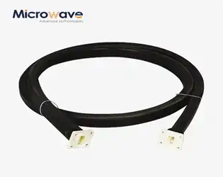
From DC to 110 GHz: How Our Waveguide Cable Assemblies Maintain Superior Signal Integrity
September 23, 2025
When critical communications fail at 110 GHz frequencies, the consequences can be catastrophic. Imagine a defense radar system losing target acquisition during a critical mission, or a satellite communication link dropping vital data transmission precisely when it's needed most. These scenarios highlight the paramount importance of maintaining exceptional signal integrity across the entire frequency spectrum from DC to 110 GHz. In today's demanding high-frequency applications, engineers face the constant challenge of preserving signal quality while minimizing loss, crosstalk, and interference. Our Waveguide Cable Assembly solutions address these critical pain points by delivering uncompromising performance that ensures your most sensitive applications maintain reliable, crystal-clear signal transmission even under the most demanding conditions.
How a Waveguide High Pass Filter Solves Your Low-Frequency Noise Problems?
September 23, 2025
In today's complex microwave and RF systems, engineers face a persistent challenge: low-frequency noise contaminating critical high-frequency signals, leading to degraded performance, signal distortion, and system failures. The Waveguide High Pass Filter emerges as the definitive solution to this pervasive problem, offering precision filtering capabilities that eliminate unwanted low-frequency interference while preserving essential high-frequency signal integrity. Understanding how these sophisticated components work and their transformative impact on system performance is crucial for engineers seeking to optimize their RF and microwave applications across satellite communications, radar systems, and defense technologies.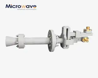
Conical Dual Circular Polarization Horn Antenna for Advanced Antenna R&D
September 22, 2025
In the rapidly evolving landscape of modern antenna research and development, the Conical Dual Circular Polarization Horn Antenna stands as a cornerstone technology that addresses the growing demands for high-performance communication systems. This sophisticated antenna solution combines cutting-edge engineering principles with practical application versatility, making it indispensable for advanced research facilities, satellite communications, and defense applications. The unique design architecture, featuring dual circular polarization capabilities within a precision-engineered conical structure, enables researchers and engineers to achieve superior signal quality while maintaining optimal performance across diverse frequency ranges. With the increasing complexity of modern communication networks and the persistent demand for enhanced signal integrity, this antenna technology represents a significant advancement in the field of microwave and millimeter-wave research and development.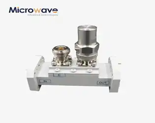
How to Customize Double-Ridged Waveguide Loop Couplers for Your Exact Frequency Needs?
September 22, 2025
In today's demanding microwave and RF landscape, engineers face the critical challenge of finding precise coupling solutions that match their exact frequency specifications. Whether you're developing satellite communication systems, radar applications, or advanced telecommunications infrastructure, the wrong Double-Ridged Waveguide Loop Coupler can lead to signal degradation, increased insertion loss, and system failures that cost both time and resources. The question isn't just about finding a coupler – it's about securing one that delivers optimal performance across your specific frequency range while maintaining the coupling accuracy and directivity your application demands. This comprehensive guide addresses the exact customization process that transforms a standard Double-Ridged Waveguide Loop Coupler into a precision-engineered solution tailored to your frequency requirements, helping you avoid costly mismatches and achieve superior system performance.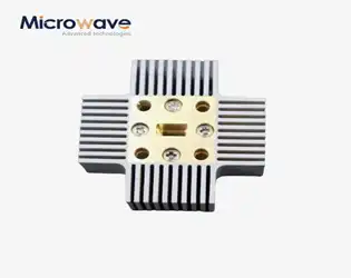
Stop Signal Loss: How Hermetic Waveguide Windows Block Moisture and Contaminants
September 22, 2025
Imagine your critical satellite communication system suddenly experiencing 20-50% signal degradation during a crucial mission due to moisture infiltration in the waveguide assembly. This nightmare scenario affects thousands of engineers daily, where environmental contaminants cause devastating performance losses in microwave systems. The solution lies in understanding how hermetic waveguide pressure windows create an impenetrable barrier against moisture and contaminants while maintaining optimal signal transmission. Advanced Microwave's Waveguide Pressure Window technology addresses this critical challenge by providing robust environmental protection without compromising electromagnetic performance, ensuring your systems maintain peak efficiency in the harshest operating conditions.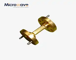
Circular Straight Waveguide: The Low-Loss Choice for Aerospace Innovation
September 19, 2025
Aerospace engineers face a critical challenge: ensuring reliable signal transmission in extreme environments where even minimal signal loss can compromise mission success. When every decibel matters and system reliability determines life-or-death outcomes, choosing the right waveguide technology becomes paramount. The Circular Straight Waveguide emerges as the definitive solution, offering unparalleled low-loss characteristics specifically engineered for aerospace innovation, where traditional transmission methods simply cannot meet the demanding requirements of modern aircraft, satellites, and space exploration systems.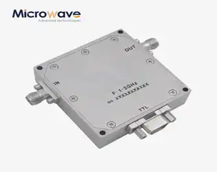
Customizable Digitally Controlled Phase Shifter Solutions for Aerospace and Defense Applications
September 19, 2025
In today's rapidly evolving aerospace and defense landscape, mission-critical systems demand unprecedented precision in signal control and beam steering capabilities. When radar systems fail to maintain accurate target tracking due to phase inconsistencies, or when satellite communication links suffer from signal degradation during critical operations, the consequences can be catastrophic. The Digitally Controlled Phase Shifter emerges as the cornerstone solution for these challenges, offering precise phase adjustment capabilities that ensure optimal system performance. These advanced microwave components provide the digital precision and reliability required for next-generation phased array antennas, radar systems, and communication networks where signal integrity can determine mission success or failure.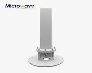
Unlock Cost Savings: Reduce Testing Space by 60% with Compact Probes
September 19, 2025
Are you struggling with escalating laboratory costs while facing increasing pressure to deliver precise antenna measurements? Traditional testing facilities demand extensive floor space, expensive infrastructure, and substantial operational overhead that can drain budgets and limit scalability. The solution lies in revolutionary compact Antenna Near Field Measurement Probe technology that transforms how organizations approach microwave testing. This comprehensive guide reveals how modern compact probes can dramatically reduce your testing space requirements by up to 60% while maintaining measurement accuracy and reliability, offering unprecedented cost savings for businesses across satellite communications, aerospace, defense, and telecommunications industries.
