BLOG
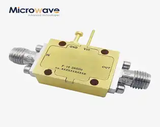
Voltage Controlled Phase Shifter: The Key to Low-Loss, High-Precision RF Control
January 8, 2026
In modern RF and microwave systems, signal degradation and phase misalignment can cripple performance, leading to poor beamforming accuracy, unreliable satellite communications, and compromised radar detection. Engineers working with phased array antennas, aerospace navigation systems, and defense electronics face a critical challenge: how to achieve precise phase control without introducing excessive insertion loss or signal distortion. The Voltage Controlled Phase Shifter emerges as the solution to this pain point, offering dynamic phase adjustment capabilities that maintain signal integrity while enabling real-time beam steering and system calibration across demanding applications from DC to 40 GHz.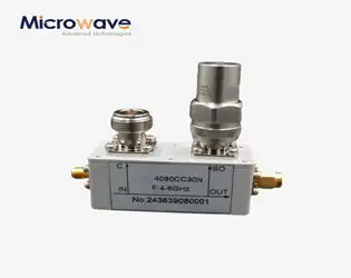
What is a coaxial directional coupler?
January 8, 2026
In modern RF and microwave systems, signal integrity can make or break critical operations. Whether you're managing satellite ground stations where signal degradation means lost data transmissions, operating radar systems where detection accuracy depends on precise power monitoring, or maintaining telecommunication networks where even minor signal losses impact performance, understanding coaxial directional couplers becomes essential. A Coaxial Directional Coupler is a passive four-port device that samples a predetermined portion of electromagnetic power traveling through a transmission line, enabling signal monitoring, measurement, and processing without disrupting the main signal path. This fundamental component ensures engineers can measure forward and reflected power, monitor transmission quality, and protect sensitive equipment across frequencies ranging from DC to millimeter-wave bands.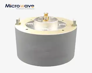
How to Choose the Best Planar Spiral Antenna for Multi-Band Use?
January 8, 2026
When designing modern communication systems that demand operation across multiple frequency bands simultaneously, engineers face a critical challenge: selecting an antenna that delivers consistent performance without requiring multiple hardware configurations. The Planar Spiral Antenna emerges as the definitive solution for multi-band applications, offering exceptional bandwidth coverage from 1 GHz to 40 GHz while maintaining stable impedance characteristics and circular polarization throughout its operational range. This comprehensive guide examines the essential criteria for selecting the optimal Planar Spiral Antenna configuration, addressing the technical specifications, performance parameters, and practical considerations that determine success in satellite communications, aerospace defense systems, electronic reconnaissance, and advanced telecommunications infrastructure.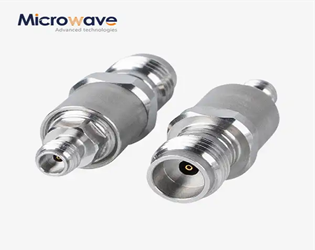
Why Every RF Installation Needs a Premium Coaxial Cable Adapter?
January 6, 2026
Picture this scenario: your satellite communication system is operational, your defense radar equipment is configured perfectly, and your aerospace navigation system meets all technical specifications. Then disaster strikes during signal transmission when incompatible connectors create catastrophic signal degradation, costing thousands in downtime and potentially compromising mission-critical operations. This nightmare becomes reality when RF installations lack premium Coaxial Cable Adapters. These precision-engineered components serve as the critical connectivity backbone for transmitting radio frequency signals with minimal loss, ensuring seamless integration between different connector types, impedances, and system configurations while maintaining signal integrity across frequencies from DC to 40 GHz.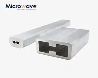
What Are the Main Components of a Double Ridge Waveguide Tube?
January 6, 2026
When designing high-frequency microwave systems for satellite communications, radar installations, or 5G networks, engineers face a critical challenge: achieving wide bandwidth transmission without sacrificing signal integrity. The Double Ridge Waveguide Tube addresses this challenge through its specialized internal structure, which consists of precisely engineered ridges, metal housing, flanges, and surface treatments. Understanding these main components is essential for optimizing system performance and ensuring reliable electromagnetic wave propagation across frequencies ranging from 1 GHz to 110 GHz in demanding aerospace, defense, and telecommunications applications.
Top Double‑Ridged Waveguide Loop Coupler Features You Must Know
January 6, 2026
When high-power RF systems fail due to inadequate power monitoring or signal degradation across wide frequency ranges, engineers face costly downtime and system failures. The Double-Ridged Waveguide Loop Coupler addresses these critical challenges by providing reliable power sensing, exceptional bandwidth coverage, and stable performance in demanding microwave applications. Understanding the essential features of this component is crucial for anyone working in satellite communications, radar systems, aerospace, or telecommunications where signal integrity and system reliability are non-negotiable.
Buy OEM Log Periodic Antenna: What to Look For
December 31, 2025
Imagine deploying a critical satellite ground station only to discover your antenna can't handle the full frequency range your system requires. Or perhaps you're managing a defense radar installation where signal degradation threatens mission-critical surveillance operations. These scenarios plague engineers and procurement managers who underestimate the complexity of selecting the right Log Periodic Antenna for their applications. When you buy OEM Log Periodic Antenna solutions, you're not just purchasing hardware—you're investing in broadband performance, system reliability, and operational flexibility across diverse frequency bands. This comprehensive guide reveals the critical factors that separate exceptional Log Periodic Antenna systems from inadequate ones, helping you make informed decisions that protect your investment and ensure mission success.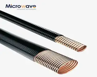
Are Elliptical Waveguide Antennas Better for Narrow Beams?
December 31, 2025
Imagine your satellite ground station struggling to maintain a stable connection during critical data transmission, or your radar system failing to distinguish between closely spaced targets in high-density environments. These aren't hypothetical scenarios—they're the daily challenges faced by engineers working with high-frequency microwave systems. The answer to whether Elliptical Waveguide antennas deliver superior narrow beam performance lies in understanding their unique electromagnetic properties and how their geometry fundamentally shapes signal propagation, offering significantly enhanced directivity and precision compared to traditional circular or rectangular waveguide configurations in applications demanding ultra-narrow beamwidths.


